Method and apparatus to compensate for supply voltage variations in a PWM-based voltage regulator

a voltage regulator and pulse width technology, applied in the direction of electric variable regulation, process and machine control, instruments, etc., can solve the problem of significant delay in this type of pulse width correction, the ramp voltage cannot step instantaneously to follow and correct for a fast supply voltage transient, and the feedback loop is relatively slow for stable operations

Active Publication Date: 2011-01-11
MICROSEMI CORP
View PDF28 Cites 23 Cited by
  • Summary
  • Abstract
  • Description
  • Claims
  • Application Information

AI Technical Summary

Benefits of technology

[0007]In one embodiment, the present invention proposes a PWM controller that adjusts an error signal (or a PWM control signal) inversely with respect to a supply voltage to quickly compensate for changes or transients in the supply voltage. The PWM controller generates at least one output signal that drives one or more semiconductor switches in a switching voltage regulator. The switching voltage regulator receives the supply voltage and generates a regulated output voltage for a load. The regulated output voltage level depends on the supply voltage level and duty cycle (or pulse width) of the output signal from the PWM controller. The duty cycle of the output signal from the PWM controller is controlled in part by an error signal in a feedback loop. The ability to quickly adjust the error signal in response to transients in the supply voltage helps to maintain a substantially constant regulated output voltage without undesirable overshoots or undershoots caused by fluctuations or sudden changes in the supply voltage.

Problems solved by technology

However, the feedback loop is relatively slow for stable operations and does not usually react fast enough to rapid changes (or transients) in the DC supply voltage to prevent overshoots or undershoots in the regulated output voltage.
There is generally significant delay in this type of pulse width correction since the slope of the ramp signal is generally controlled by a current charging a capacitor, and voltage across a capacitor cannot change instantaneously.
Since the ramp voltage (i.e., the voltage across the capacitor) cannot change instantaneously when charging current changes, the ramp voltage cannot step instantaneously to follow and correct for a fast supply voltage transient.

Method used


Image

  • Method and apparatus to compensate for supply voltage variations in a PWM-based voltage regulator
  • Method and apparatus to compensate for supply voltage variations in a PWM-based voltage regulator
  • Method and apparatus to compensate for supply voltage variations in a PWM-based voltage regulator

Examples


Embodiment Construction

[0025]Although particular embodiments are described herein, other embodiments, including embodiments that do not provide all of the benefits and features set forth herein, will be apparent to those of ordinary skill in the art.

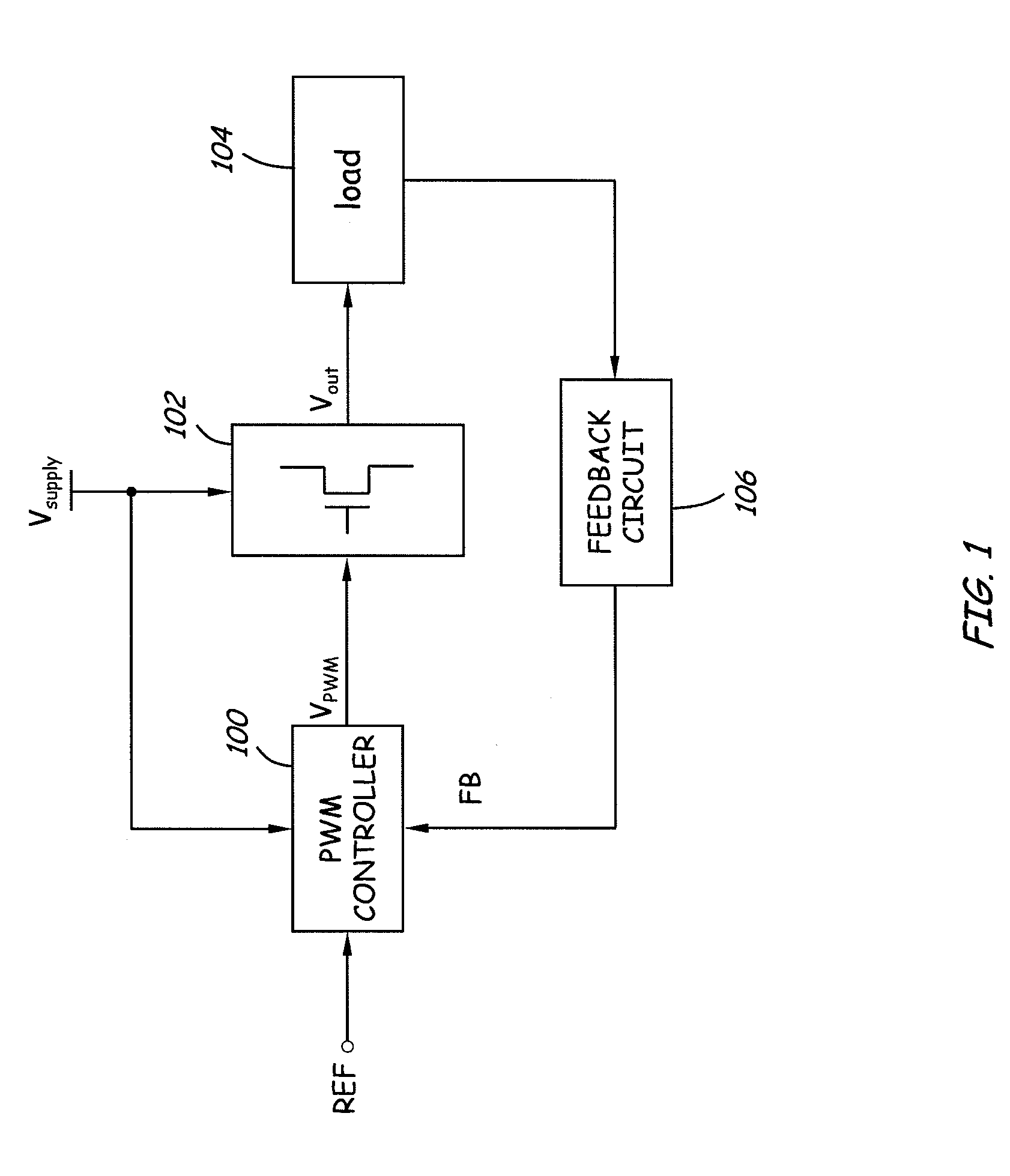
[0026]FIG. 1 is a block diagram of a switching voltage regulator according to one embodiment of the present invention. The switching voltage regulator includes a switching circuit 102 configured to receive a supply voltage (Vsupply) and to provide a regulated output voltage (Vout) to a load 104. A feedback circuit 106 senses an output condition to generate a feedback signal (FB) for a controller 100. In one embodiment, the controller 100 uses PWM techniques to generate one or more PWM driving signals (VPWM) to control one or more semiconductor switches in the switching circuit 102. The level or amplitude of the regulated output voltage is proportional to a pulse width (or duty cycle) of the PWM driving signals. The controller 100 receives a reference signal (R...


PUM


Abstract

A feed-forward correction circuit in a PWM controller adjusts an error signal inversely with respect to a supply voltage for a switching voltage regulator to quickly compensate for changes or transients in the supply voltage. The adjusted error signal is provided to a PWM comparator to control a duty cycle of an output signal. The switching voltage regulator can be a DC-to-DC converter or a DC-to-AC converter, and the output signal is used to generate one or more driving signals to control semiconductor switches in the switching voltage regulator. The feed-forward correction circuit uses an offset compensation technique or a translinear circuit to maintain a substantially inverse product relationship between the supply voltage and the duty cycle of the output signal, thereby reducing overshoots and undershoots in a regulated output voltage of the switching voltage regulator.

Description

CLAIM FOR PRIORITY[0001]This application claims the benefit of priority under 35 U.S.C. §119(e) of U.S. Provisional Application No. 60 / 849,211 entitled “Compensation for Supply Voltage Variations in a PWM” and U.S. Provisional Application No. 60 / 849,254 entitled “PWM Duty Cycle Inverse Adjustment Circuit,” both filed on Oct. 4, 2006, the entirety of which is incorporated herein by reference.BACKGROUND[0002]1. Field of the Invention[0003]The invention generally relates to a pulse width modulation (PWM) controller for a switching voltage regulator, and more particularly, relates to a feed-forward circuit that adjusts an output pulse width inversely with respect to a supply voltage to compensate for transients or changes in the supply voltage.[0004]2. Description of the Related Art[0005]A switching voltage regulator generally accepts a direct current (DC) supply voltage at a first level and generates a regulated output voltage at a second level. The second level can be higher or lower ...

Claims


Application Information

Patent Timeline
Patent Type & Authority Patents(United States)
IPC IPC(8): G05F1/46G05F1/575
CPCH02M3/156H05B39/047H05B41/3927H02M2001/0022H02M1/0022
Inventor LACOMBE, DAVID K.CHIOU, CHII-FAHENRY, GEORGE C.
Owner MICROSEMI CORP
Why Eureka
Try Eureka