Engine assembly, acoustical liner and associated method of fabrication

a technology of acoustic liner and engine, which is applied in the direction of non-positive displacement fluid engines, liquid fuel engine components, flooring insulations, etc., can solve the problems of reducing the useful life of the fan blade, generating significant noise, and affecting the structural integrity of the engine and/or nacelle structure, so as to increase the noise generated by the engine, the effect of increasing the weight of the engin

Active Publication Date: 2011-01-18
THE BOEING CO
View PDF33 Cites 25 Cited by
  • Summary
  • Abstract
  • Description
  • Claims
  • Application Information

AI Technical Summary

Benefits of technology

[0006]An engine assembly, an acoustical liner and an associated method of fabricating an acoustical liner are therefore provided according to embodiments of the present invention in order to address at least some of the issues associated with conventional designs. In this regard, embodiments of the present invention provide an acoustical liner which permits fan blade flutter to be addressed without necessarily increasing the weight of the engine, impairing the structural integrity of the engine and / or nacelle structures, or increasing the noise generated by the engine. In this regard, embodiments of the present invention provide an acoustical liner having additional acoustical degrees of freedom which permit these otherwise sometimes competing concerns to be addressed in a complementary manner. As such, embodiments of the present invention permit simultaneous tuning of the acoustical frequency response of the nacelle structures to both fan noise control and fan blade flutter control frequencies over the same areas, thereby avoiding discontinuities in acoustical impedance.
[0007]In one embodiment, an acoustical liner is provided which includes an inner barrel having a perforated face sheet, a back skin comprising a plurality of perforations and a core, such as a cellular or honeycomb core, disposed between the perforated face sheet and the back skin. The acoustical liner of this embodiment also includes an outer barrel surrounding and spaced from the inner barrel to define a space therebetween. As a result of its design, the perforations through the inner barrel back skin place the core, such as the honeycomb cells in the core, in fluid communication with the space between the inner and outer barrels. As such, the fluid communication between the core and the space between the inner and outer barrels provides additional acoustical degrees of freedom which may be utilized to simultaneously tune the liner to frequencies needed to reduce fan blade flutter and to frequencies needed to control fan blade noise.
[0008]In another embodiment, an engine assembly is provided. The engine assembly includes a fan, a compressor downstream of the fan, a combustion section downstream of the compressor and a turbine downstream of the combustion section. The engine assembly of this embodiment also includes an acoustical liner forward of and surrounding the fan, including inner and outer barrels of the nacelle inlet and / or the engine fan case. The inner barrel includes a core and a back skin disposed on the core and including a plurality of perforations. The outer barrel surrounds and is spaced from the inner barrel to define an air-filled space therebetween. As before, the perforations through the inner barrel back skin place the core such as the honeycomb cells of the core, in fluid communication with the space between the inner and outer barrels thereby providing for additional acoustical degrees of freedom for the acoustical liner.
[0009]In either embodiment, the acoustical liner may also includes at least one extension tube extending from the back skin into the space between the inner and outer barrels. The extension tube is in fluid communication with a perforation through the back skin, thereby increasing the acoustical inertia and reducing one or more natural frequencies of the acoustical liner. Additionally or alternatively, the acoustical liner may include a baffle extending from the back skin into the space between the inner and outer barrels with the baffle positioned such that at least one perforation defined by the back skin is in fluid communication with the baffle. The baffle serves to increase the acoustical stiffness of the acoustical liner, thereby tuning the acoustical liner to have higher natural frequencies. The acoustical liner and, in particular, the inner and outer barrels may be configured to have at least one natural frequency within a frequency range associated with fan blade flutter and at least one natural frequency within a frequency range associated with fan noise and fan blade-pass frequencies. As such, the additional acoustical degrees of freedom permit these natural frequencies to be tuned to concurrently address both fan blade flutter and fan noise.

Problems solved by technology

Engines, such as aircraft engines, can generate significant noise.
Such noise may be undesirable in populated areas and in other environments in which noise is desirably controlled.
In addition to the noise generated by an engine, another issue associated with turbofan engines is fan blade flutter which may reduce the useful lifetime of the fan blades and, in some situations, may cause the fan blades to fail.
In instances in which the fan blades are anticipated to flutter, the fan blades are generally scheduled to be inspected on a more frequent basis, and the lifetime of the fan blades is typically limited relative to fan blades that are not anticipated to flutter.
However, such changes are constrained by the thrust requirements for the engine, and may disadvantageously add to the weight of the aircraft or undermine the structural integrity of the nacelle.
Since the frequency at which fan blades flutter is different from the frequency of fan noise, efforts intended to modify the acoustical liner to improve fan blade flutter margin may be in conflict with the frequency response of the acoustical liner needed to reduce fan blade noise, thereby potentially leading to an increase in the fan blade noise.
Discontinuities in acoustical frequency response between regions of the nacelle structure tuned to different frequencies for noise control and fan blade flutter control, respectively, can cause significant increases in noise.
However, these acoustical resonators may conflict with the tuning of the inlet in regard to fan blade noise and result in a disadvantageous increase in the fan noise.

Method used


Image

  • Engine assembly, acoustical liner and associated method of fabrication
  • Engine assembly, acoustical liner and associated method of fabrication
  • Engine assembly, acoustical liner and associated method of fabrication

Examples


Embodiment Construction

[0018]The present inventions now will be described more fully hereinafter with reference to the accompanying drawings, in which some, but not all, embodiments of the inventions are shown. Indeed, these inventions may be embodied in many different forms and should not be construed as limited to the embodiments set forth herein; rather, these embodiments are provided so that this disclosure will satisfy applicable legal requirements. Like numbers refer to like elements throughout.

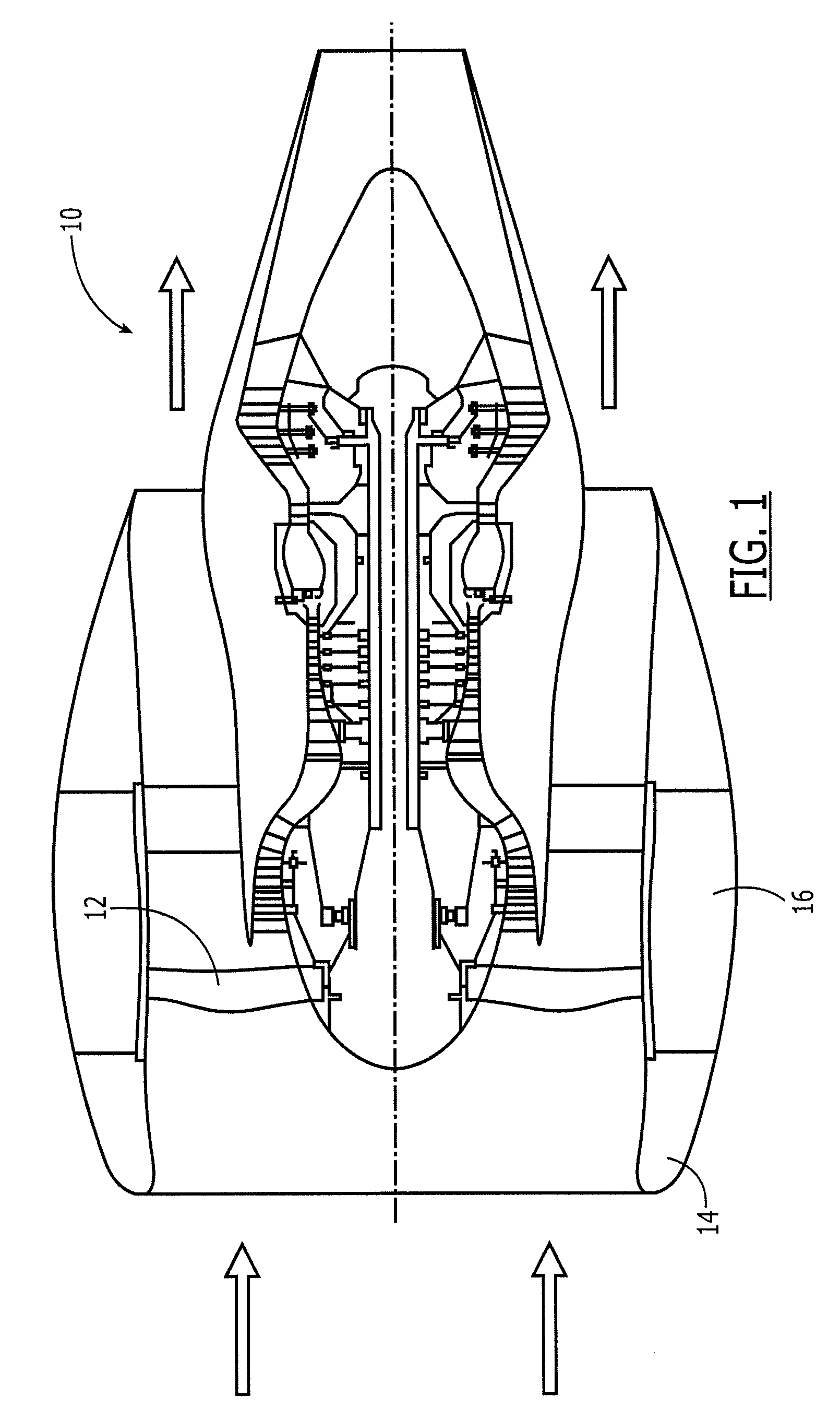
[0019]An engine assembly 10 according to one embodiment to the present invention is depicted in FIG. 1. Although described below in the context of an aircraft engine, the engine assembly can be employed in a variety of different applications, if so desired. As shown, the engine 10 may be a turbofan engine. In the illustrated embodiment, the engine includes two shafts, while other engines may include a single shaft or three or more shafts. As shown in FIG. 1, in instances in which the engine 10 is an aircraft ...


PUM

PropertyMeasurementUnit
frequencyaaaaaaaaaa
frequencyaaaaaaaaaa
volumeaaaaaaaaaa

Abstract

An engine assembly, an acoustical liner and an associated fabrication method are provided to address fan blade flutter and fan noise control simultaneously within the same liner area. Fan blade flutter is therefore controlled without necessarily increasing the weight of the engine, impairing the structural integrity of the engine, or increasing the noise generated by the engine. The acoustical liner may have additional acoustical degrees of freedom which permit these seemingly competing concerns to be addressed in a complementary manner. The acoustical liner may include inner and outer barrels with the inner barrel having a perforated face sheet, a perforated back skin and a core disposed between the perforated face sheet and the back skin. The fluid communication between the core and the space between the inner and outer barrels provides additional acoustical degrees of freedom which may be utilized to reduce fan blade flutter while concurrently limiting fan blade noise.

Description

FIELD OF THE INVENTION[0001]Embodiments of the present invention are directed generally to gas turbine engine assemblies and, more particularly, to an improved acoustical liner and an associated method of fabrication for providing passive control of both fan blade flutter and fan noise.BACKGROUND OF THE INVENTION[0002]Engines, such as aircraft engines, can generate significant noise. Such noise may be undesirable in populated areas and in other environments in which noise is desirably controlled. As such, acoustical liners for inlets, fan cases, fan nozzles, and other engine installation structures have been developed to reduce the amount of noise emanating from an engine. The acoustical liners generally are disposed within the nacelle of the aircraft engine.[0003]In a turbofan engine, for example, the portion of the inlet portion of the nacelle forward of the fan includes inner and outer barrels separated by an air-filled space. In order to reduce the noise emanating from the engin...

Claims


Application Information

Patent Timeline
Patent Type & Authority Patents(United States)
IPC IPC(8): B64D33/02E04B1/82B64D33/00
CPCF02C7/045F02K1/82F23M20/005Y10T29/4957F05D2260/96Y02T50/672Y02T50/60
Inventor FARSTAD, JERRY E.
Owner THE BOEING CO
Why Eureka
Try Eureka