Relay

a relay and armature technology, applied in the field of relays, can solve the problems of difficult to secure high component accuracy and assembling accuracy, high assembling accuracy of armatures, and varied operation characteristics of relays, and achieve excellent high-frequency characteristics

Inactive Publication Date: 2011-01-18
ORMON CORP
View PDF21 Cites 25 Cited by
  • Summary
  • Abstract
  • Description
  • Claims
  • Application Information

AI Technical Summary

Benefits of technology

According to the present embodiment, since shielding can be achieved with the magnetic shielding sheet, a relay having excellent high-frequency characteristics is obtained.

Problems solved by technology

However, since the armature is positioned to the drivers through the frame, there is a limitation in that the armature is assembled to the sub-base with high assembling accuracy.
In particular, since the frame has a complicated shape and is required to be manufactured by means of press work, it is difficult to secure high component accuracy and assembling accuracy.
As a result, a problem arises that operation characteristics of a relay are varied.

Method used


Image

  • Relay
  • Relay
  • Relay

Examples


Embodiment Construction

Description of the Numerals

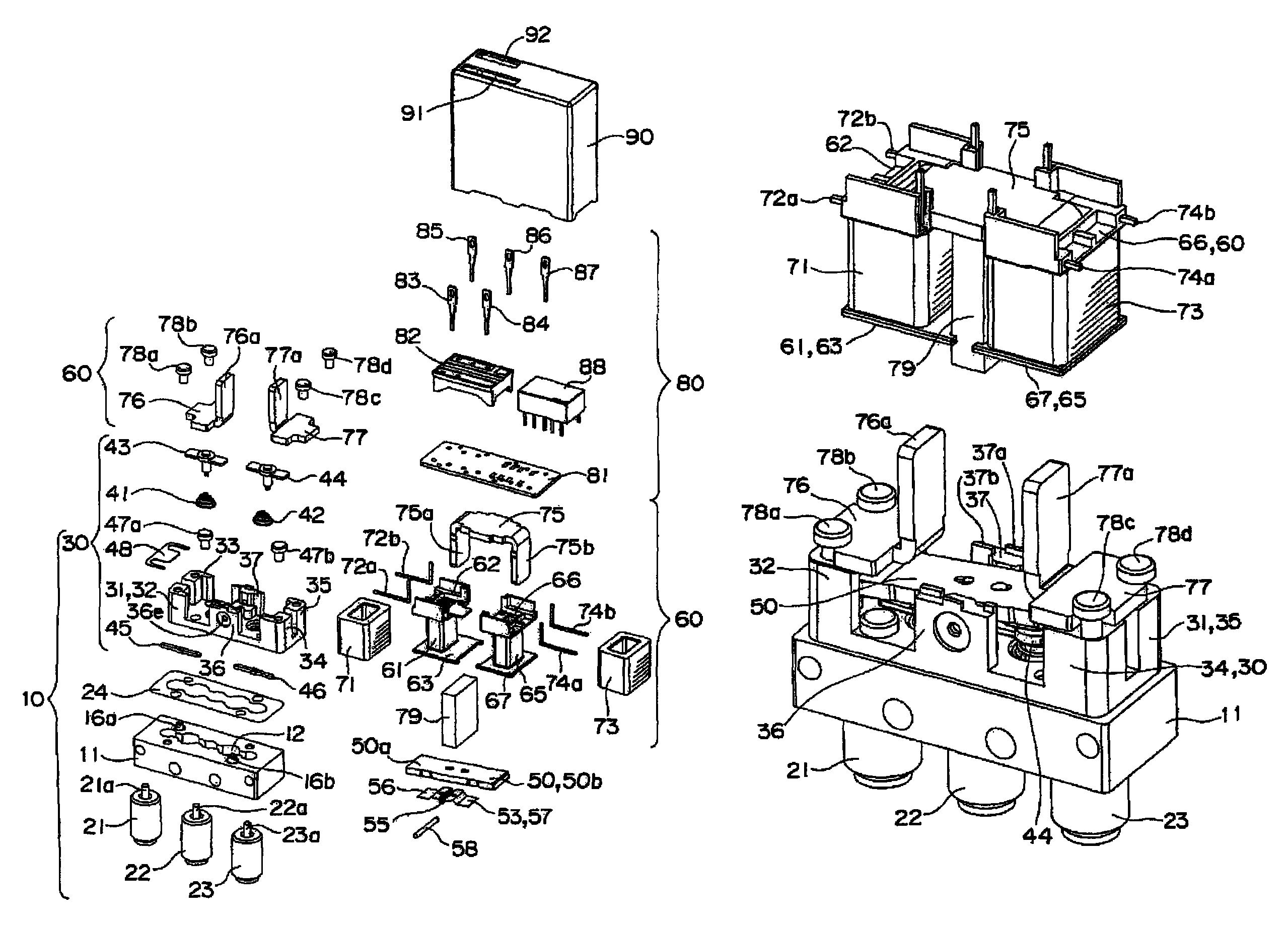
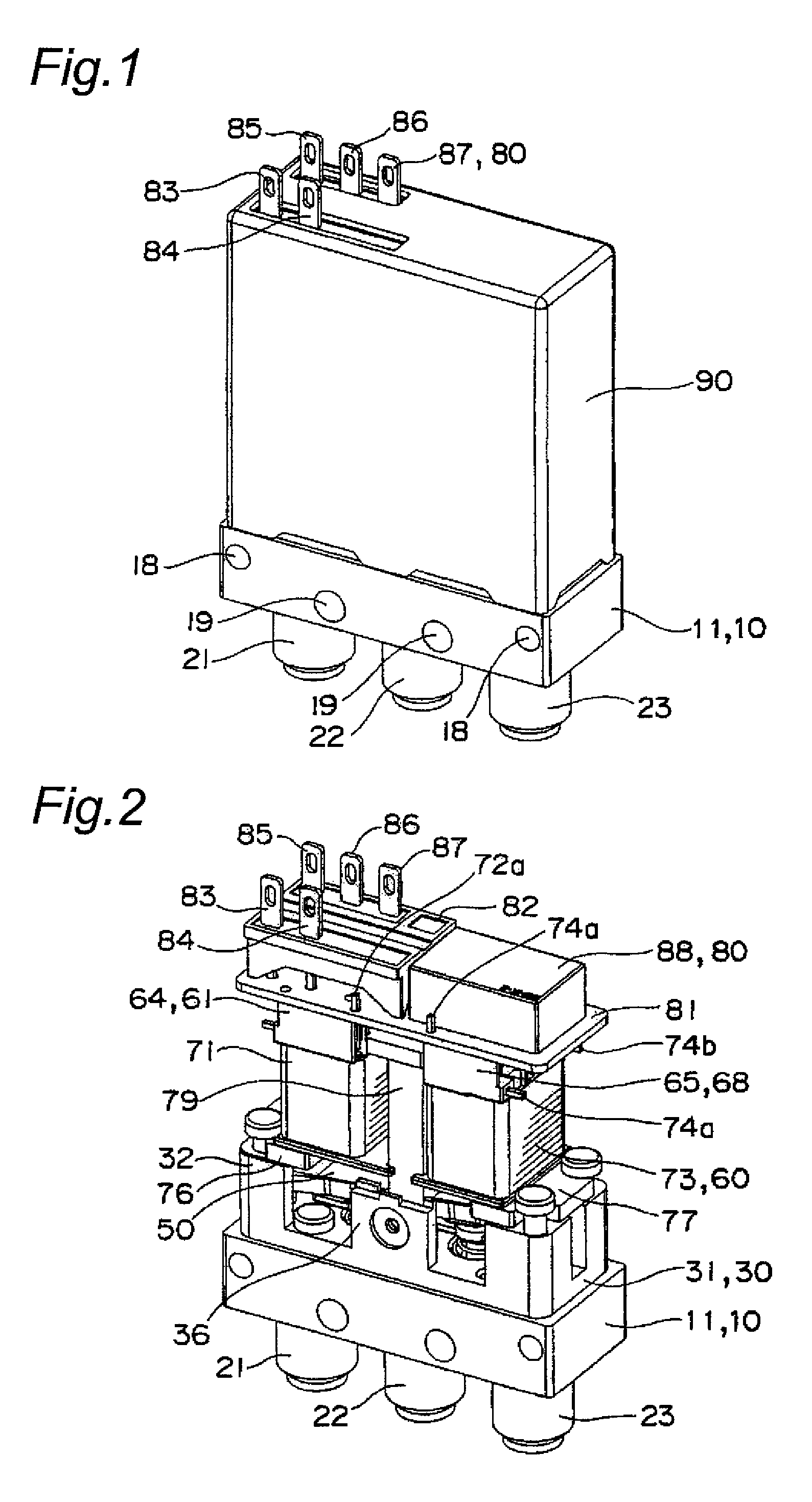
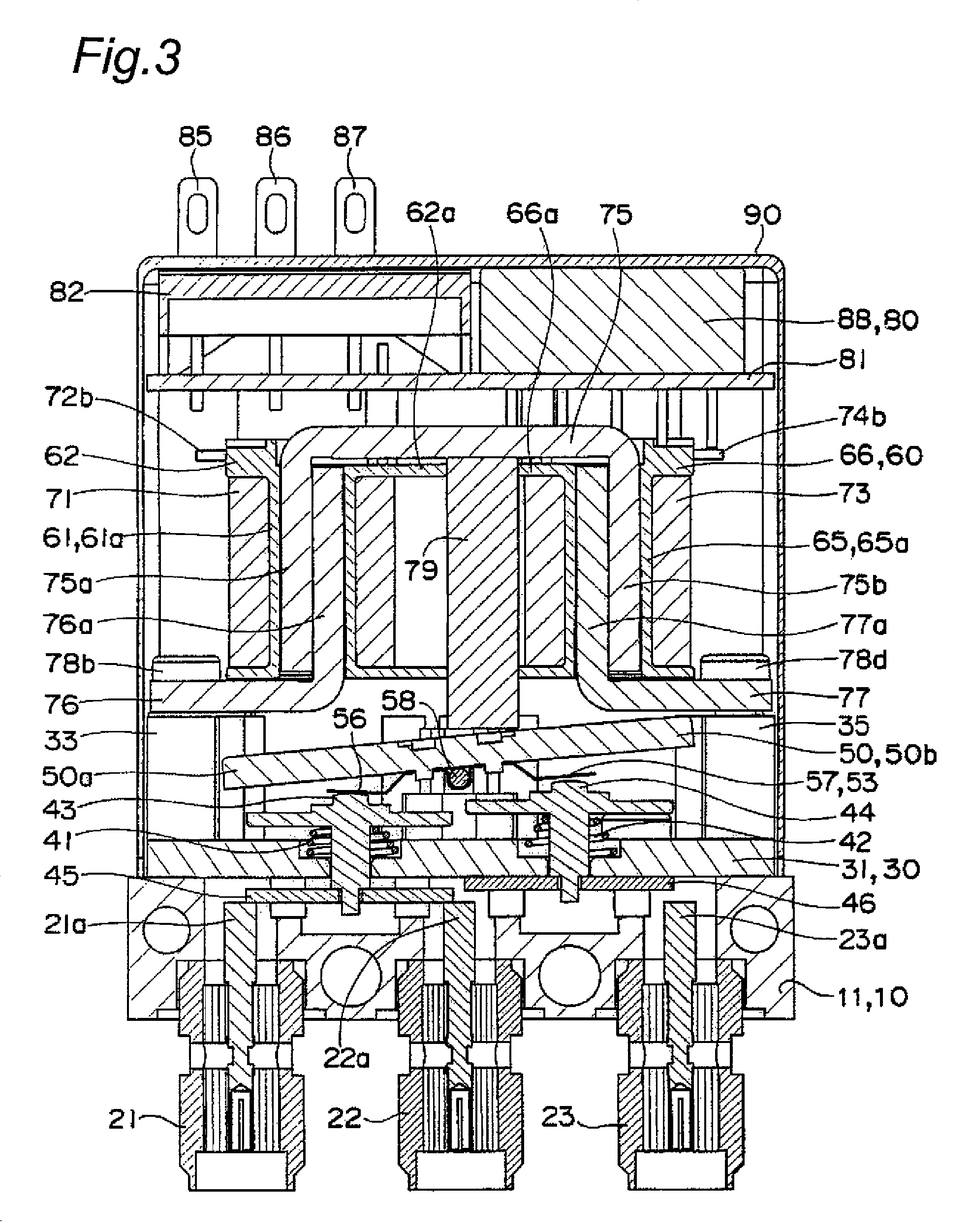
10: contact point unit11: base block12: escape groove13, 14, 15: through holes for coaxial connectors16a, 16b: positioning pins18, 19: attachment through holes21, 22, 23: coaxial connectors21a, 22a, 23a: fixed contact points24: copper sheet30: contact point block31: contact point base31a, 31b: operation holes32, 33, 34, 35: supporting posts36, 37: supporting walls36a, 36b, 36c, 37a, 37b, 37c: positioning projections36d, 37d: position restricting protrusions36e, 37e: shaft holes41, 42: coil springs43, 44: plungers45, 46: movable contact points45a, 46a: caulk openings45b: engagement recess50: movable iron piece53: plate spring55: bearing portion55a: shaft hole56, 57: elastic arm portions58: supporting shaft60: electromagnetic unit61, 65: self-resetting type first, second spools61a, 65a: body portions61b, 65b: through holes62, 63, 66, 67: flange portions62a, 66a: positioning tongues64, 68: positioning walls69: self-holding spool71, 73: coils72a, 72b, 74a, 74b...


PUM


Abstract

A relay includes a contact point block having a support shaft with both ends spanning a contact point base, a plunger having a movable contact at a lower end thereof, and a movable iron piece configured to drive the plunger and to have a plate spring. The relay also includes an electromagnetic unit and a base block having a fixed contact point at a position opposite to the movable contact point. The movable iron piece is supported on the supporting shaft. The plunger is inserted through an operation hole of the contact point base. Upper and lower surfaces of the contact point block are held by the electromagnetic unit and the base block. The electromagnetic unit directly fixes the iron core to an upper surface of the contact point base.

Description

FIELD OF INVENTIONThe present invention relates to a relay, in particular, to a high-frequency relay used for broadcast equipment and measurement equipment.BACKGROUNDIn a high-frequency relay, for example, there is a coaxial relay as shown in FIGS. 3 and 8, in which a frame 27 welded to side surfaces of a sub-base 4 is formed with ribs 43 by means of press work, the ribs 43 are loosely fitted into square openings 42 of an armature spring 19 which is integrated with an armature 2, an upper surface of the armature spring 19 is brought into contact with a dowel 49 protrusively provided on a lower surface of a protruding piece 48 of the frame 27 so as to be freely rotatable, and drivers (plungers) 16 whose lower portions are integrated with contacts 5 are supported on the sub-base 4 in a manner so as to be movable up and down, and both end portions of the armature 2 alternately drive the plungers 16 as shown in FIG. 1 and FIG. 2 (see Patent Document 1).That is, while the drivers and the...

Claims


Application Information

Patent Timeline
Patent Type & Authority Patents(United States)
IPC IPC(8): H01H53/00H01H3/00H01H67/02
CPCH01H50/041H01H50/10H01H50/34H01H50/54H01H51/2272H01H49/00H01H2011/0075
Inventor NAKAMURA, MASANORISARUWATARI, YOJIROSHINOURA, TATSUOOTA, AKIRA
Owner ORMON CORP
Why Eureka
Try Eureka