System for and method of providing a wide-range flow controller

a flow sensor and wide-range technology, applied in the field of system and method of providing a wide-range flow controller, can solve the problems of limiting the range in which a particular flow sensor can be effectively employed, affecting the efficiency of flow sensor operation, and affecting the accuracy of flow sensor at the lower end of the flow range, so as to improve the signal-to-noise ratio of flow sensor, improve the effect of mass flow controller turn-down ratio, and low set-points

Active Publication Date: 2011-01-25
BROOKS INSTRUMENT
View PDF72 Cites 28 Cited by
  • Summary
  • Abstract
  • Description
  • Claims
  • Application Information

AI Technical Summary

Benefits of technology

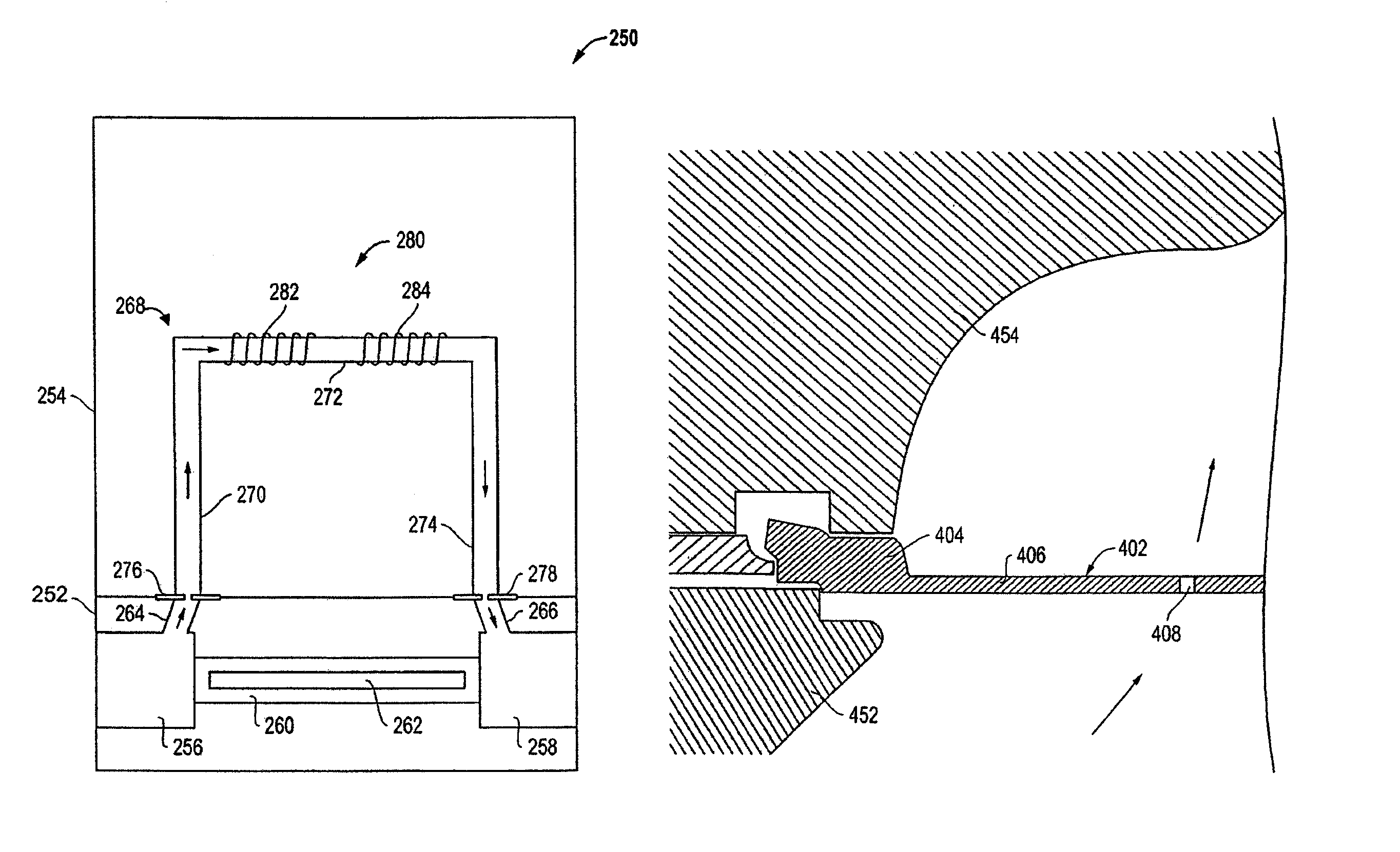
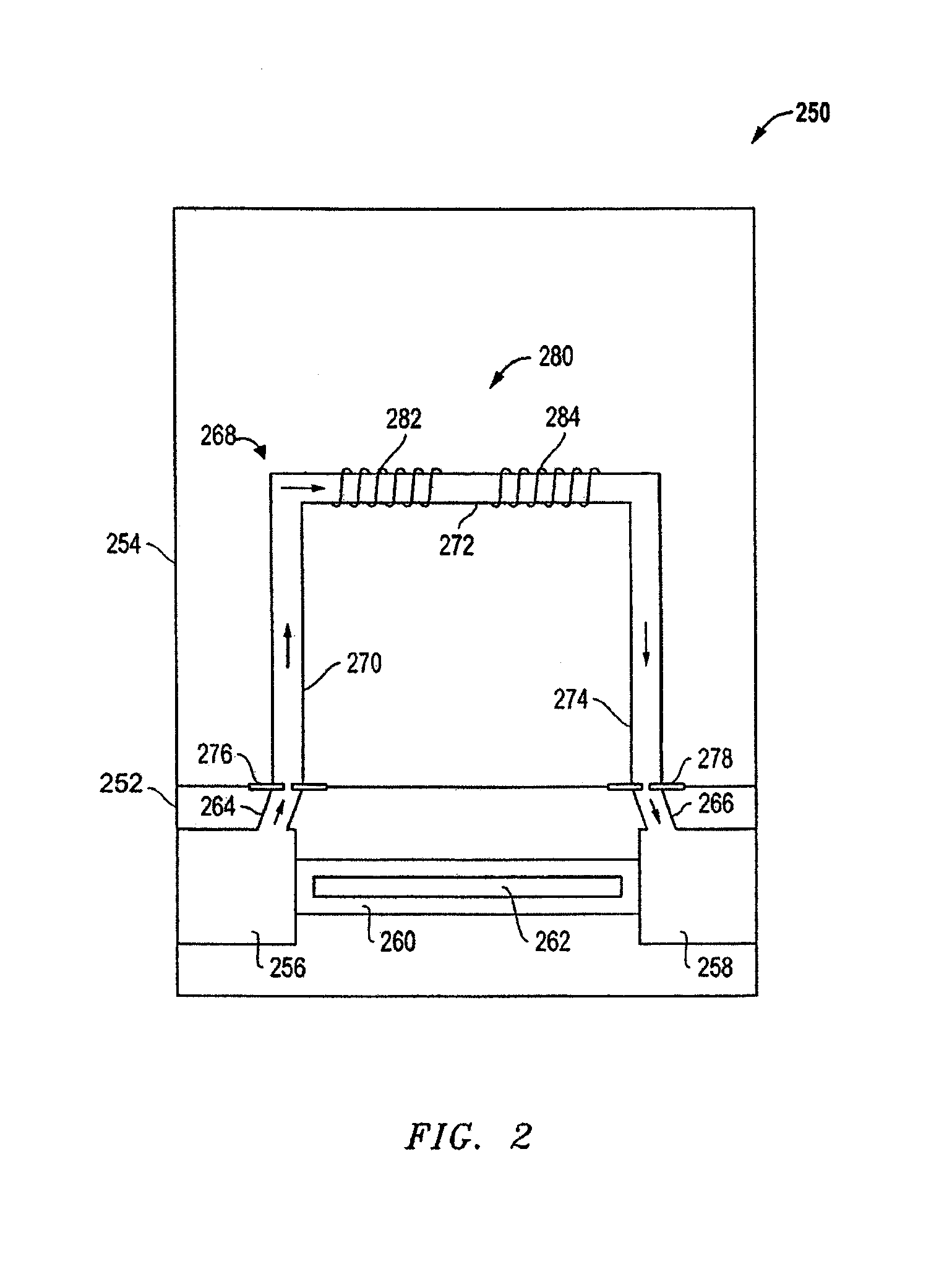
[0014]According to some embodiments of the invention, the introduction of an orifice with a nonlinear pressure-flow relationship in the sensor fluid flow path improves the signal to noise ratio of the flow sensor at low set-points. Further, theses embodiments may improve the mass flow controller's turn-down ratio resulting in a mass flow controller with a usable range that is at least an order of magnitude greater than previously known flow sensors.

Problems solved by technology

This traditional approach results in greater accuracy at higher flow rates (relative to the full scale range) with decreasing accuracy at the lower end of the flow range of the flow sensor.
The decrease in accuracy at the low end of the flow sensor range limits the range in which a particular flow sensor can be effectively employed.
To meet present standards for accuracy, thermal mass flow sensors are typically restricted to a relatively small usable range.

Method used


Image

  • System for and method of providing a wide-range flow controller
  • System for and method of providing a wide-range flow controller
  • System for and method of providing a wide-range flow controller

Examples


Embodiment Construction

[0034]A flow measuring device, such as a mass flow meter or mass flow controller, according to the present invention provides a high turn-down ratio as compared to conventional devices. A turn-down ratio of the overall mass flow controller (MFC) can be defined as a ratio between an amount of fluid flow through the mass flow controller at the maximum operable sensor set-point (which is typically 100% of the full-scale flow as determined above) and an amount of fluid flow through the mass flow controller at the minimum operable sensor set-point. As described in greater detail below, the random noise and the specified error of a sensor can be used to determine the minimum operable sensor set-point. The turn-down ratio provides an indication of the usable range of the mass flow controller. Accordingly, a large turn-down ratio is indicative of a mass flow controller that can measure and control the flow of fluid, within a required accuracy, over a wide range of flows.

[0035]In accordance ...


PUM


Abstract

An improved flow measuring device, such as a mass flow meter or mass flow controller, providing a high turn-down ratio as compared to prior art devices. In accordance with various embodiments of the invention, a flow sensor includes a sensor flow path that includes one or more restrictions configured to provide the sensor flow path with a non-linear relationship between a pressure drop across the sensor flow path and the flow of fluid through the flow sensor conduit. Such a flow sensor preferably achieves a high turn-down ratio by way of a variable bypass ratio that is directly proportional to the sensor tube mass flow rate so that the turn-down ratio of the mass flow controller will be ideally proportional to the square of the turndown achievable by the flow sensor conduit fluid sensing portion alone. In some embodiments, the restriction can be employed as a part of a fluid seal having an orifice and disposed between a flow sensor portion of a flow meter and a bypass portion of the flow meter.

Description

[0001]This application claims priority from U.S. Provisional Application No. 60 / 978,956 filed on Oct. 10, 2007, which is hereby incorporated by reference.TECHNICAL FIELD OF THE INVENTION[0002]Embodiments of the invention generally relate to systems and methods of measuring and / or controlling flows, and in particular, to flow sensors and flow controllers that can be used to measure and control flow over a wide range of flow rates.BACKGROUND OF THE INVENTION[0003]Many industrial processes require precise flow sensing and control of various process fluids. For example, in the pharmaceutical and semiconductor industries, mass flow sensors and mass flow controllers are used to precisely measure and control the amount of a process fluid that is introduced to a process chamber. The term fluid is used herein to describe any type of matter in any state that is capable of flow. It is to be understood that the term fluid applies to liquids, gases, and slurries comprising any combination of mat...

Claims


Application Information

Patent Timeline
Patent Type & Authority Patents(United States)
IPC IPC(8): G01F5/00G01F1/68
CPCG01F1/6842G01F5/00G05D7/0635
Inventor REDEMANN, ERIC J.WANG, CHIUNMAGINNIS, THOMAS OWEN
Owner BROOKS INSTRUMENT
Why Eureka
Try Eureka