Post boost control power assembly

a power assembly and power technology, applied in the direction of instruments, machines/engines, cosmonautic vehicles, etc., can solve the problem of gas loss and heat loss

Inactive Publication Date: 2011-01-25
NAVY U S NAVY AS REPRESENTED BY THE SEC OF THE
View PDF7 Cites 10 Cited by
  • Summary
  • Abstract
  • Description
  • Claims
  • Application Information

AI Technical Summary

Benefits of technology

[0003]The disclosed post boost control power assembly has tubular gas distributors. Each tubular gas distributor is connected to two gas generators. Each tubular gas distributor is also connected to an integrated thruster valve assembly. Each tubular gas distributor sends gas directly from a connected gas generator into a single integrated thruster valve assembly. Since gas passes directly through the tubular gas distributor, the gas remains at a high temperature. There is minimal heat loss from the gas that passes through the tubular gas distributor.
[0004]The gas that passed through a tubular gas distributor produces a more powerful force than is the force that is produced by gas that comes from a manifold, since there is less heat loss from the disclosed post boost control power assembly than from a past post boost control power assembly.
[0010]The use of four tubular gas distributors in a post boost control power assembly provides for less heat loss from gas coming from four single gas generators, than does a post boost control power assembly that uses a manifold connected to the four single gas generators. Therefore greater efficiency in position, attitude and velocity control is produced by the disclosed post boost control power assembly than was available in the past, since the force produced by gas from the tubular gas distributors is greater, and of longer duration, than is a force produced by gas that passes through a manifold.
[0011]A benefit of the tubular gas distributors, as compared to the prior art manifold, is enhanced by a bulkhead inserted in the center of each dual gas generator. The bulkhead within each dual gas generator allows for eight gas generators being within the disclosed post boost control power assembly.
[0014]The combined tubular gas distributor, close / open valve and first and second gas generator provide for a more direct gas flow to an integrated thruster valve assembly, than is provided to an integrated thruster valve assembly by a combined manifold and single gas generator. Further, the gas pressure decrease, due to heat loss, is lessened by use of a gas distributor rather than a manifold.

Problems solved by technology

Heat was lost from the gas, since the gas was sent through the manifold.

Method used


Image

  • Post boost control power assembly
  • Post boost control power assembly

Examples


Embodiment Construction

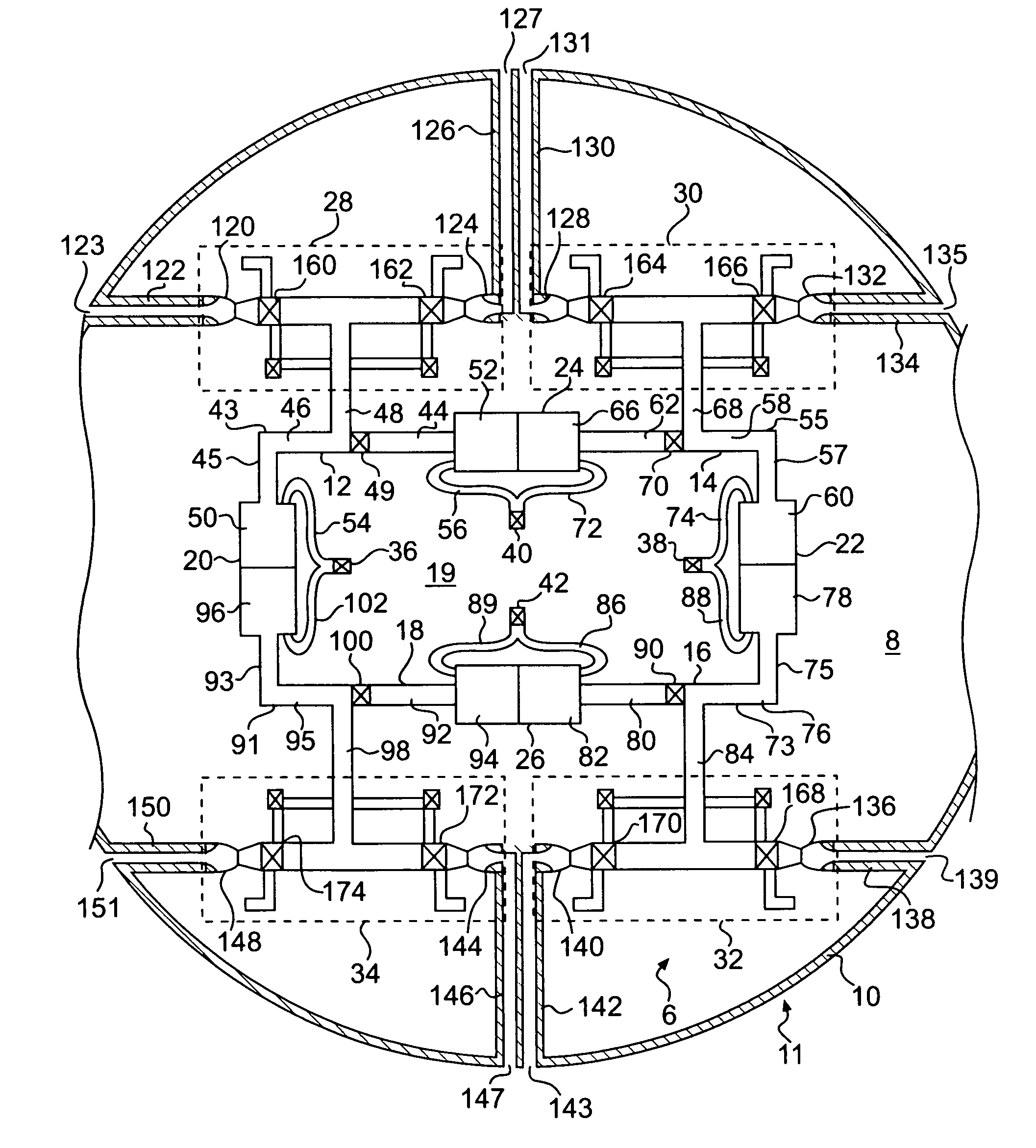
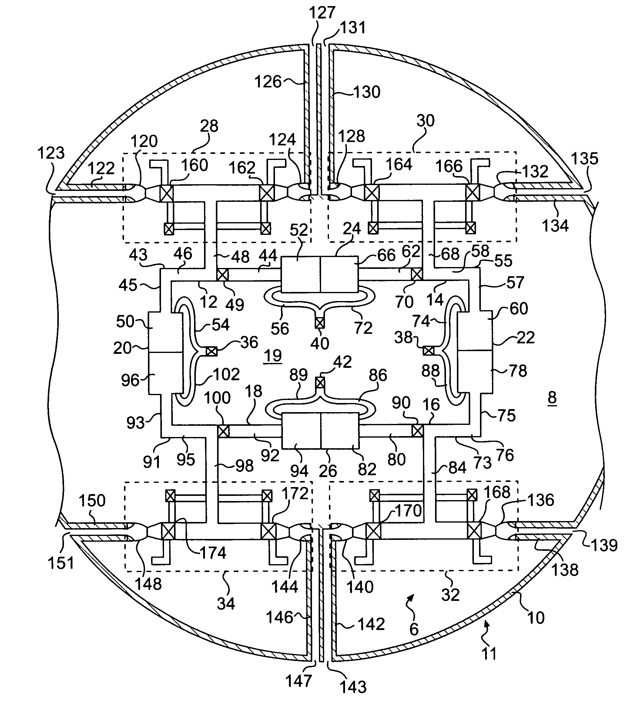
[0016]FIGURE shows a post boost control power assembly 6. The assembly 6 is connected to an aft section 8 of a missile body 10 of a missile 11. The assembly 6 has four tubular gas distributors 12, 14, 16 and 18. The assembly 6 has four dual gas generators 20, 22, 24 and 26. The assembly 6 has four integrated thruster valve assemblies 28, 30, 32 and 34. Four ignition igniters 36, 38, 40 and 42 are connected to the four dual gas generators 20, 22, 24 and 26.

[0017]The assembly 6 forms a loop 19 of four tubular gas distributors 12, 14, 16 and 18 within aft section 8 of missile body 8. The loop 19 is made possible due to a shape of each of the tubular gas distributor 12, 14, 16 and 18.

[0018]Tubular gas distributor 12 has three hollow tubular sections, namely a right-angled hollow tubular first section 46, a hollow tubular second section 48 and a hollow tubular third section 44. The tubular gas distributor 12 has a gas flow close / open valve 49 that is located within hollow tubular third s...


PUM


Abstract

A tubular distributor in a missile having a right-angled hollow tubular first section, the right-angled hollow tubular first section having a first leg and a second leg, a straight hollow tubular second section, an end of the first leg of the right-angled hollow tubular first section perpendicularly connected to a first end of the hollow tubular second section, a straight hollow tubular third section, a first end of the hollow tubular third section perpendicularly connected to the first end of the straight hollow tubular second section, and a close / open valve positioned within the straight hollow tubular third section, the close / open valve positioned between a gas generator and the straight hollow tubular second section.

Description

BACKGROUND OF THE INVENTION[0001]In the past, a post boost control power assembly had a manifold that distributed gas to several integrated thruster valve assemblies. Such a manifold is shown in U.S. Pat. No. 4,550,888. In the '888 patent, the gas was enclosed in the manifold, before the gas was sent from the manifold into the integrated valve assemblies. The gas was used to produce forces on the integrated thruster valve assemblies, as the gas passed out of the integrated thruster valve assemblies. The forces were uses to control position, attitude and velocity of a final stage of a multi-stage rocket.[0002]The manifold of the '888 patent obtained gas from a gas generator. Heat was lost from the gas, since the gas was sent through the manifold. The loss of heat from the gas, causing the gas to produce less powerful forces than might be needed for proper propulsion for position, attitude and velocity control. The cooled gases were sent to integrated thruster valve assemblies from th...

Claims


Application Information

Patent Timeline
Patent Type & Authority Patents(United States)
IPC IPC(8): F42B15/01B64G1/42F42B15/00
CPCF02K9/52F02K9/58F02K9/805F02K9/95F42B10/663
Inventor STARKEN, GEORGE M.
Owner NAVY U S NAVY AS REPRESENTED BY THE SEC OF THE
Why Eureka
Try Eureka