Large force and displacement piezoelectric MEMS lateral actuation

a piezoelectric mems and lateral actuator technology, applied in piezoelectric/electrostrictive device details, piezoelectric/electrostrictive/magnetostrictive devices, piezoelectric/electrostriction/magnetostriction machines, etc., can solve the problem of large negative (into the plane) deflection of standard piezoelectric mems unimorph actuators, and the general performance of standard piezoelectric m

Inactive Publication Date: 2011-01-25
ARMY UNITED STATES OF AMERICA AS REPRESENTED BY
View PDF1 Cites 7 Cited by
  • Summary
  • Abstract
  • Description
  • Claims
  • Application Information

AI Technical Summary

Problems solved by technology

Moreover, piezoelectric MEMS devices typically permit extremely large displacements; approximately hundreds to thousands of microns, at very low voltages.
However, integrated MEMS devices do not share this characteristic and often the degree of freedom of the actuator has a dramatic impact on its design.
Therefore, the standard piezoelectric MEMS unimorph actuator 1 is typically unable to attain large negative (into the plane) deflections.
These existing lateral piezoelectric MEMS actuators have utilized undesirable methods for increasing piezoelectric actuator stroke length, either in terms of lost work efficiency, or in chip area required to leverage the basic actuation stroke and are generally subject to variation in performance due to residual stress deformation.

Method used


Image

  • Large force and displacement piezoelectric MEMS lateral actuation
  • Large force and displacement piezoelectric MEMS lateral actuation
  • Large force and displacement piezoelectric MEMS lateral actuation

Examples


Embodiment Construction

[0046]The embodiments herein and the various features and advantageous details thereof are explained more fully with reference to the non-limiting embodiments that are illustrated in the accompanying drawings and detailed in the following description. Descriptions of well-known components and processing techniques are omitted so as to not unnecessarily obscure the embodiments herein. The examples used herein are intended merely to facilitate an understanding of ways in which the embodiments herein may be practiced and to further enable those of skill in the art to practice the embodiments herein. Accordingly, the examples should not be construed as limiting the scope of the embodiments herein.

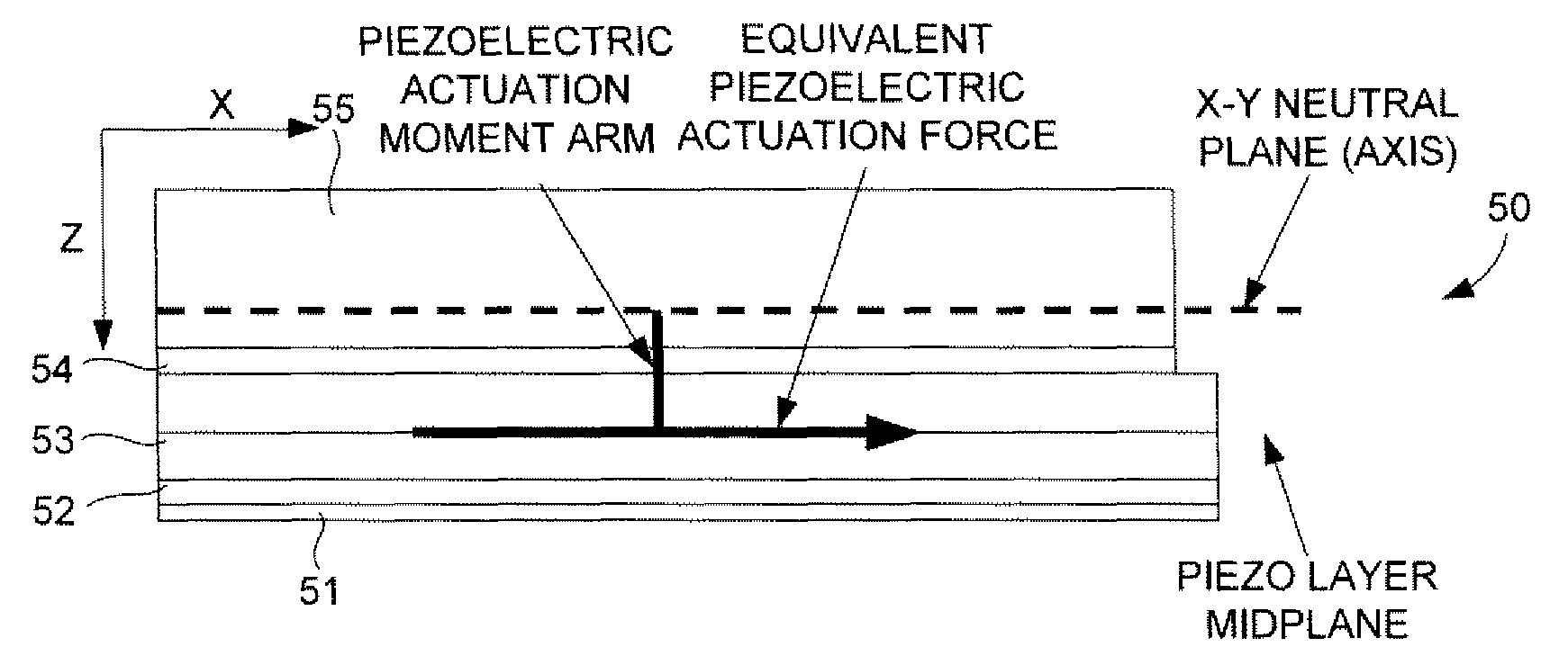
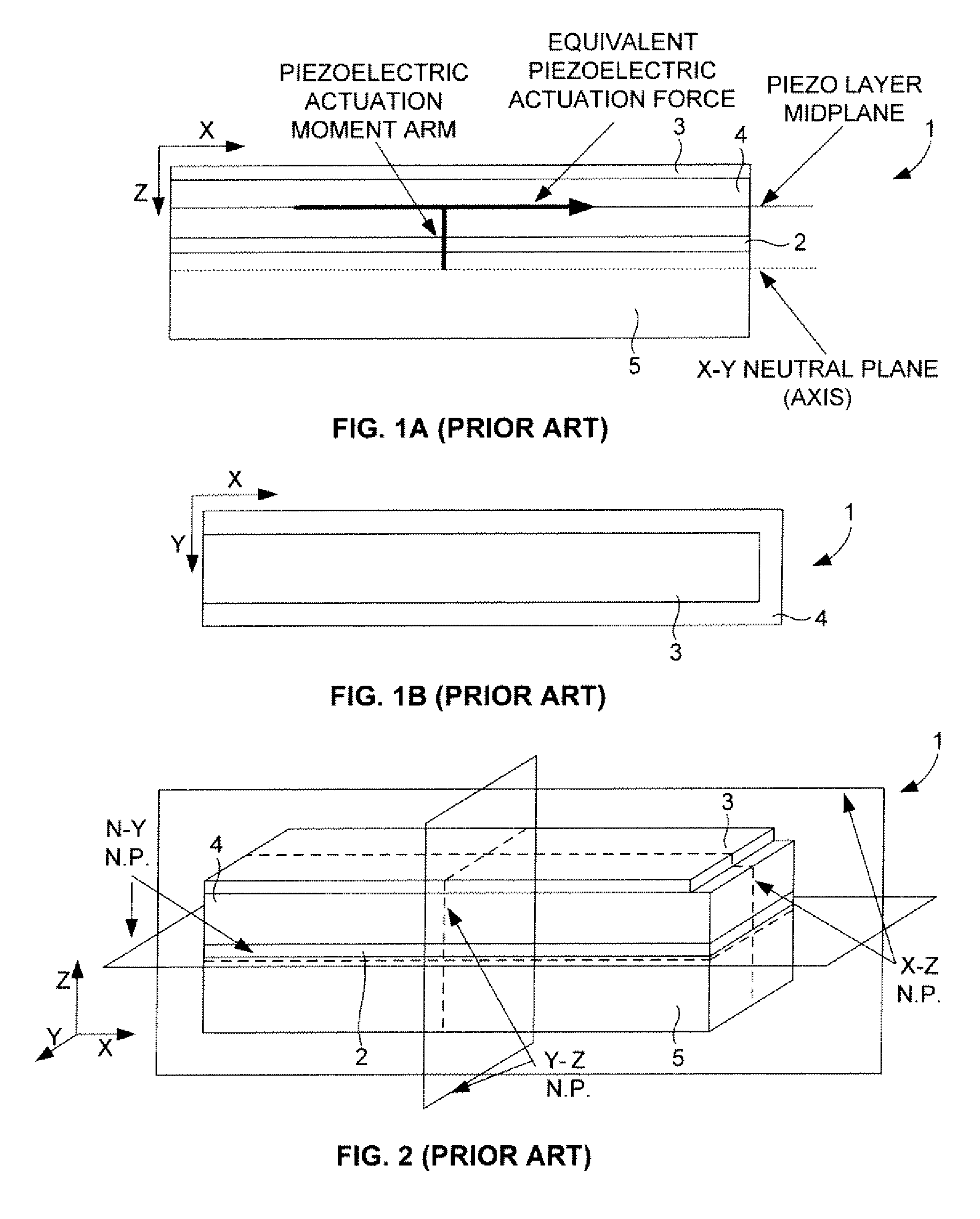
[0047]The embodiments herein provide a piezoelectric MEMS actuator that can produce significant lateral displacement and force by configuring the central section of a piezoelectric MEMS beam as a positive or negative deflection actuator and the remaining sections of the MEMS beam as the opposit...


PUM


Abstract

A piezoelectric microelectromechanical systems (MEMS) actuator includes a silicon substrate; an actuator beam comprising a first end region connected to the silicon substrate and a second end region connected to a mechanically compliant spring assembly; a first electrode over the silicon substrate; a piezoelectric layer above the first electrode; a second electrode over the piezoelectric layer; a conductive top structural layer above the second electrode, wherein a center half of the actuator beam is configured as a positive deflection region, and wherein both the first electrode and the second electrode supply voltage to both positive and negative deflection regions of the actuator beam.

Description

GOVERNMENT INTEREST[0001]The embodiments described herein may be manufactured, used, and / or licensed by or for the United States Government without the payment of royalties thereon.BACKGROUND[0002]1. Technical Field[0003]The embodiments herein generally relate to microelectromechanical systems (MEMS), and, more particularly, to piezoelectric MEMS actuators.[0004]2. Description of the Related Art[0005]MEMS piezoelectric actuators are the basic building blocks for complex electromechanical systems such as radio frequency (RF) MEMS, optical switching, robotics, and many more applications. Generally, piezoelectric MEMS actuators significantly outperform the present standard—electrostatic MEMS actuators, at significantly smaller sizes, power consumption, actuation voltages, and displacement ranges. Moreover, piezoelectric MEMS devices typically permit extremely large displacements; approximately hundreds to thousands of microns, at very low voltages.[0006]Conventional piezoelectric MEMS ...

Claims


Application Information

Patent Timeline
Patent Type & Authority Patents(United States)
IPC IPC(8): H01L41/04
CPCH01L41/0933H02N2/043H01L41/319H01L41/332H10N30/2041H10N30/079H10N30/082
Inventor PULSKAMP, JEFFREY SPENCERPOLCAWICH, RONALD G.
Owner ARMY UNITED STATES OF AMERICA AS REPRESENTED BY
Why Eureka
Try Eureka