Method for adjusting a working unit of a harvesting machine

a harvesting machine and working unit technology, applied in the field of harvesting machine working unit adjustment, can solve the problems of not being adapted to the current harvesting process of the harvesting machine and/or its working unit, still relatively difficult for operators to adjust the machine, and inexperienced and/or untrained operators

Inactive Publication Date: 2011-02-01
CLAAS SELBSTFAHRENDE ERNTEMASCHINEN GMBH
View PDF4 Cites 49 Cited by
  • Summary
  • Abstract
  • Description
  • Claims
  • Application Information

AI Technical Summary

Benefits of technology

[0006]The object of the present invention, therefore, is to create an alternative control method for adjusting a working unit of a harvesting machine and a corresponding harvesting machine that makes it easy for even relatively untrained operators to adjust the working units of the harvesting machine according to the particular harvesting process in a reliable, optimum manner, even when the adjustment-related dependencies are very complex.
[0014]In a technically very simple method it is possible, e.g., for the pictures or picture series to be displayed to an operator of the harvesting machine for selection. In this case, the selection unit must include a suitable display device to display the pictures or picture series taken at various setting states, and a recording device for recording a selection command made by the operator. Modern harvesting machines typically include appropriate user interfaces anyway with a suitable display and operating elements, which can be used within the framework of the present invention. At least some of the pictures or picture series are preferably displayed to the operator in parallel, so that he can identify the better setting state by directly comparing the pictures or picture series and select the corresponding picture or picture series. In this case, the analysis is therefore carried out by the operator of the harvesting machine simply by his comparing pictures.
[0015]It is also possible to automatically analyze the pictures or picture series taken at various setting states and to subsequently select the picture or picture series based on the analysis result. To this end, the harvesting machine must include a related analytical unit, which can be realized, e.g., in the form of software loaded in a suitable programmable control device. An automatic analysis of this type can be carried out with the aid of typical image-evaluation methods, e.g., with an object detection method. To this end, certain picture features can be stored in a memory, it being possible to use the picture features in an image evaluation as characteristic features for detecting certain particles, e.g., straw parts or husks, in the picture of the crop-material flow. In this manner, it is therefore possible, e.g., to easily count the number of “foreign objects” in the crop-material flow that are visible in the picture and, based thereon, to determine a quality level, e.g., a contamination level, of the damaged-grain portion, or to make an unspecific quality assessment such as “good”, “poor” or “acceptable”, etc. of the crop-material flow depicted.

Problems solved by technology

Despite the many aids offered by the manufacturers of harvesting machines to help operators perform adjustments—such as comprehensive operator training, printed lists of setting values predetermined for various harvesting situations that the operator can refer to, and electronic tools such as electronic fieldwork information systems preprogrammed with optimized combinations of setting values for highly diverse harvesting situations for the operator to choose from—it is still relatively difficult for operators to adjust the machine such that it functions in an optimum manner according to the desired requirements.
This is the case, in particular, for inexperienced and / or untrained operators, particularly at the beginning of a harvesting season.
In many cases, therefore, the harvesting machine and / or its working units are not adapted to the current harvesting process in an optimum manner.
As a result, the available harvesting capacity of the machine is under-utilized, poor operating results are obtained, or, in some cases, unnecessary crop losses result.
The entire image evaluation and control method is relatively complex, however.

Method used


Image

  • Method for adjusting a working unit of a harvesting machine
  • Method for adjusting a working unit of a harvesting machine
  • Method for adjusting a working unit of a harvesting machine

Examples


Embodiment Construction

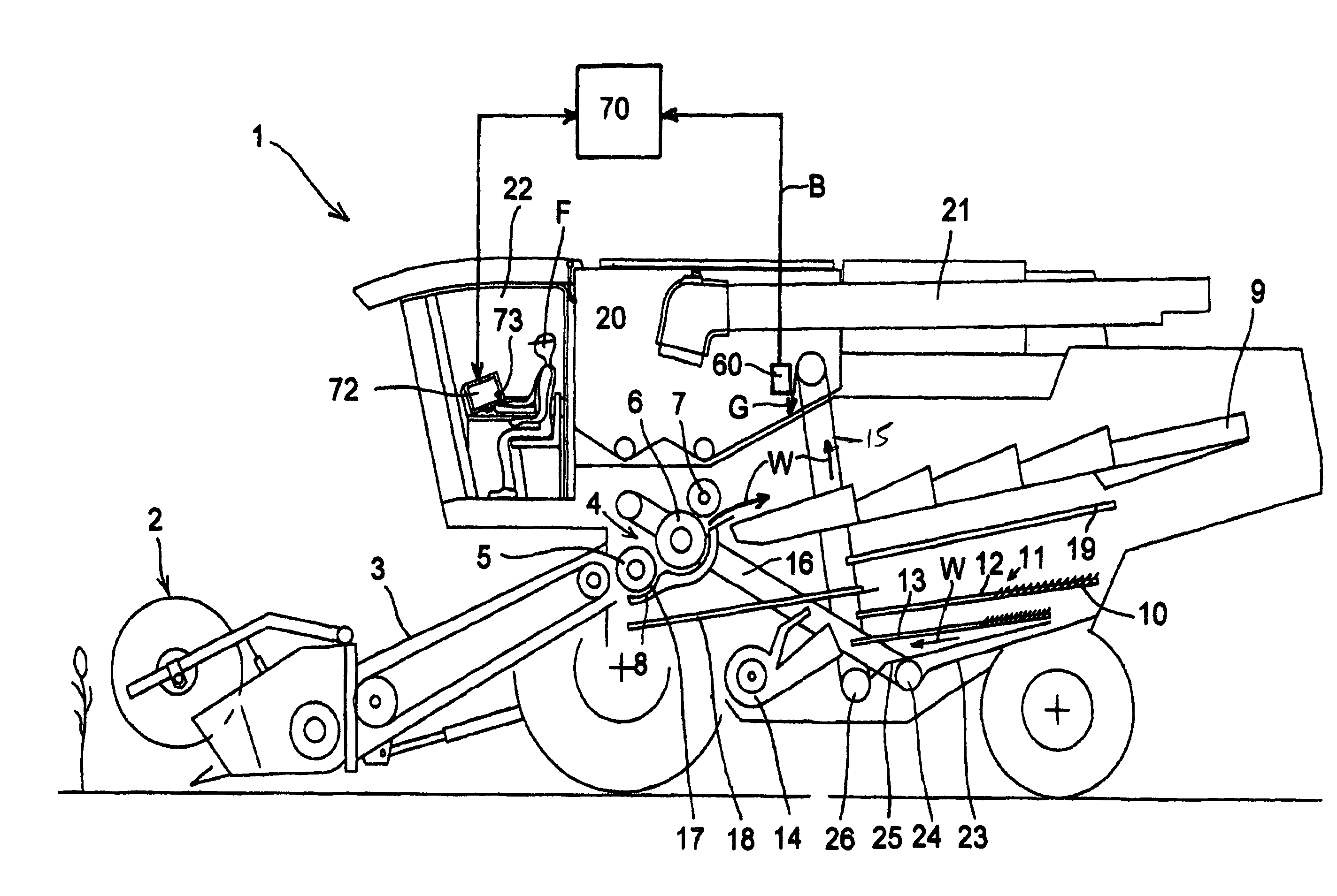
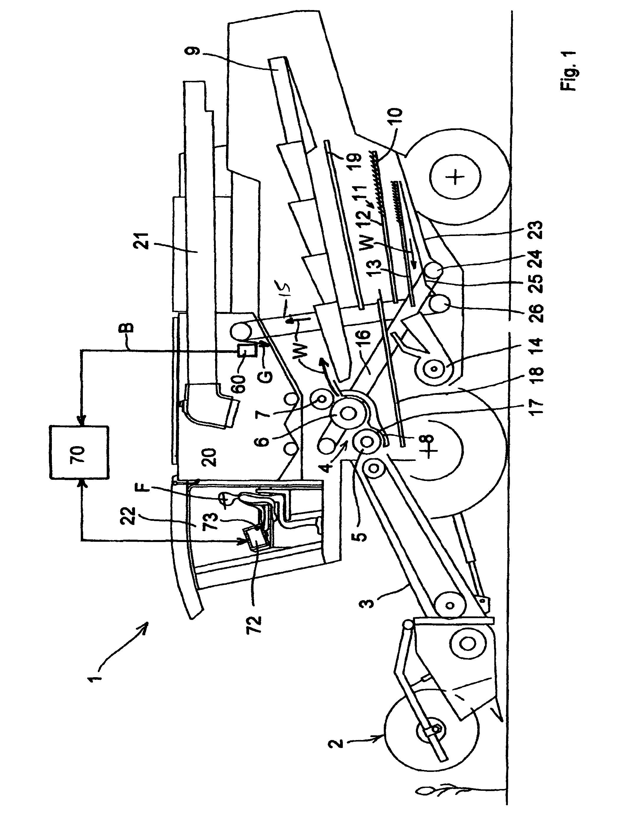
[0029]The exemplary embodiment of the present invention shown in FIG. 1 is a self-propelled combine harvester 1 with a tangential or cross-flow threshing mechanism 4 and a straw walker 9 located behind it, as the separating unit. A cleaning unit 11 is located beneath straw walker 9, cleaning unit 11 being composed of two sieves 12, 13 located one on top of the other, and a blower 14. The present invention is expressly not limited to combine harvesters of this type, however.

[0030]The crop material is initially taken up by a header 2, which conveys the crop material to a feed rake 3. Feed rake 3 transfers the crop material to counterclockwise-rotating threshing parts 5, 6, 7 of threshing unit 4. The crop material coming out of feed rake 3 is initially captured by a preacceleration cylinder 5 and is pulled further by a cylinder 6 through threshing gap 17 that is the gap between preacceleration cylinder 5 or cylinder 6 and concave 8 located beneath it. Cylinder 6 processes the crop mate...


PUM


Abstract

A method of adjusting at least one working unit of a harvesting machine includes taking pictures or picture series of a crop-material flow at a position downstream from a particular working unit in a crop-material conveyance path at various setting states with certain control parameter setting values of the working unit, storing the pictures or picture series such that they are assigned to control parameter setting values belonging to a particular setting state, with which a picture or a picture series is selected based on an analysis of the crop-material flow depicted in the picture or picture series, and adjusting the particular working unit using the control parameter setting values assigned to the selected picture or the selected picture series; and a harvesting machine carries out the method.

Description

CROSS-REFERENCE TO A RELATED APPLICATION[0001]The invention described and claimed hereinbelow is also described in German Patent Application DE 10 2005 043 991.8 filed on Sep. 14, 2005. This German Patent Application, whose subject matter is incorporated here by reference, provides the basis for a claim of priority of invention under 35 U.S.C. 119(a)-(d).BACKGROUND OF THE INVENTION[0002]The present invention relates to a method for adjusting a working unit of a harvesting machine, in particular a self-propelled harvesting machine. The present invention also relates to a harvesting machine, with which at least one of the working units is adjustable according to a method of this type.[0003]Agricultural harvesting machines, in particular self-propelled harvesting machines such as combine harvesters, forage harvesters, etc., include several adjustable working units for processing various types of crops. With modern harvesting machines, the individual units are typically equipped with ad...

Claims


Application Information

Patent Timeline
Patent Type & Authority Patents(United States)
IPC IPC(8): A01D41/127
CPCA01D41/127A01D41/1277
Inventor BEHNKE, WILLI
Owner CLAAS SELBSTFAHRENDE ERNTEMASCHINEN GMBH
Why Eureka
Try Eureka