
Engine cooling flow debris cleaner and air pre-cleaner aspirator

a technology of engine cooling flow and debris cleaner, which is applied in the direction of liquid degasification, lighting and heating apparatus, separation processes, etc., can solve the problems of reducing the efficiency of the engine, clogging of air filters alone, and limitations on its effectiveness

Inactive Publication Date: 2011-02-01
DEERE & CO
View PDF6 Cites 19 Cited by
  • Summary
  • Abstract
  • Description
  • Claims
  • Application Information

AI Technical Summary

Benefits of technology

The system achieves consistent and efficient removal of particles with minimal parasitic losses, maintaining constant engine cooling air flow and reducing engine efficiency variability, independent of power output demands.

Problems solved by technology

An air filter alone would quickly become clogged.
Problems can occur with an arrangement of this type since the connection to the exhaust system has the potential of increasing back pressure and thereby decreasing the efficiency of the engine.
However this too has limitations on its effectiveness.

Method used


Image

  • Engine cooling flow debris cleaner and air pre-cleaner aspirator
  • Engine cooling flow debris cleaner and air pre-cleaner aspirator
  • Engine cooling flow debris cleaner and air pre-cleaner aspirator

Examples


Embodiment Construction

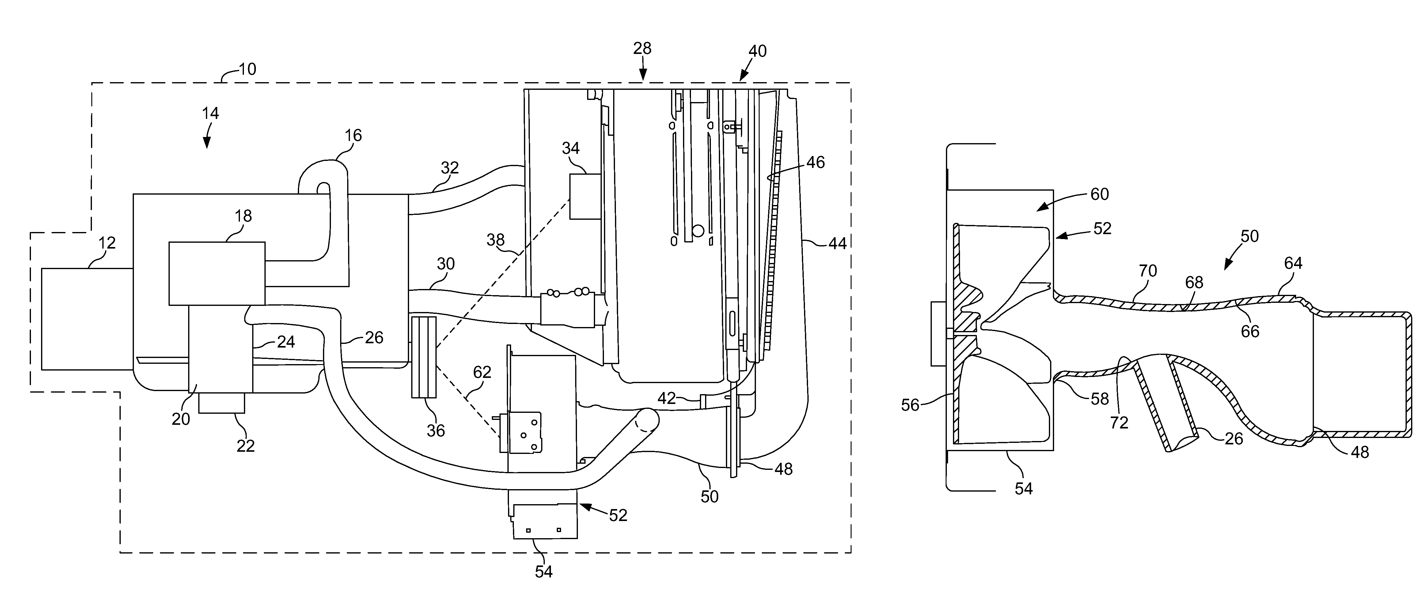
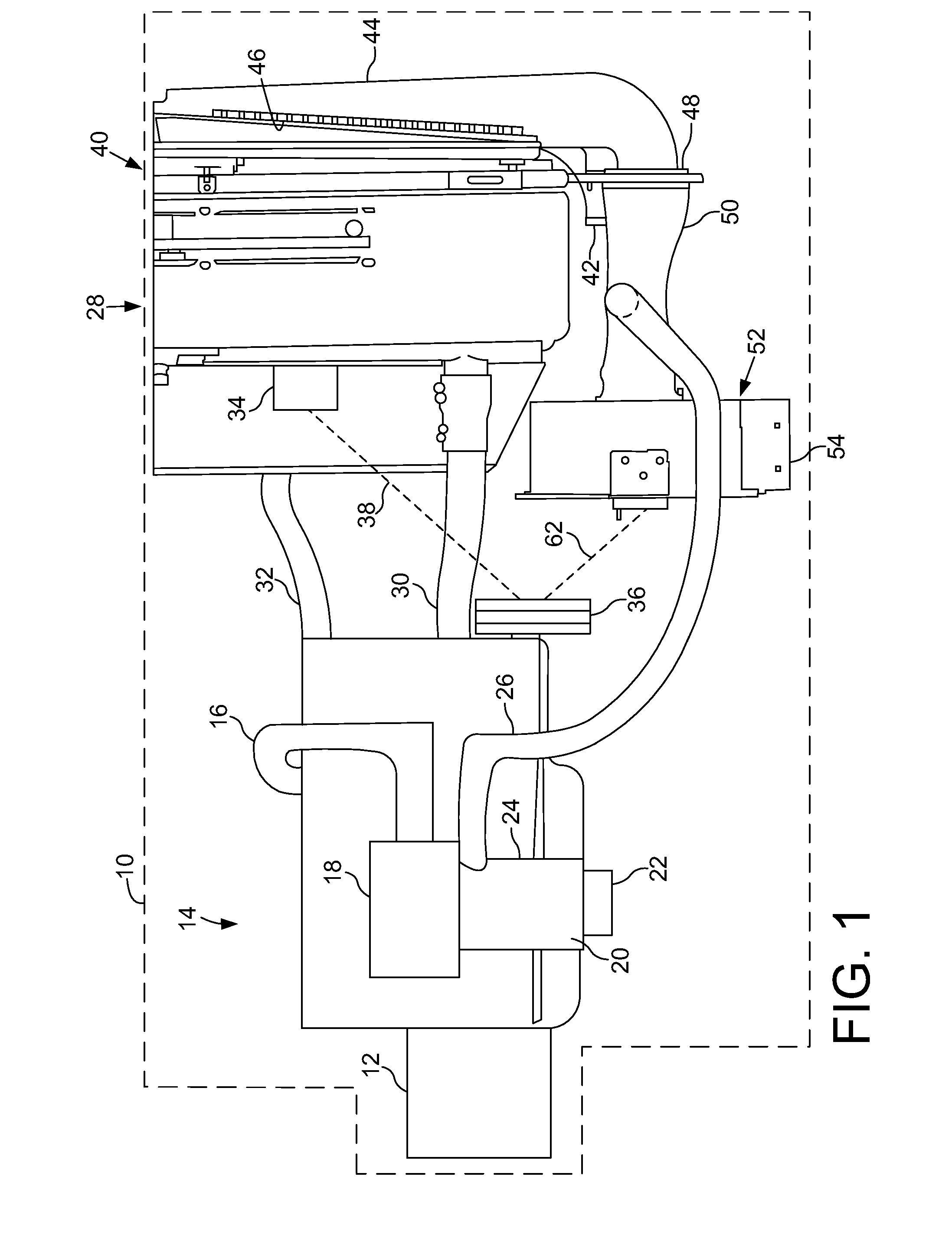
[0010]Referring to FIG. 1, there is shown a portion of a work machine 10 in the form of an agricultural vehicle, particularly the rear end drive train of the vehicle. Although shown as an agricultural vehicle it is possible the work machine 10 could be in the form of a different type of work machine such as a construction or forestry vehicle.

[0011]Work machine 10 includes a transmission 12 providing motive power for the work machine as well as powering agricultural crop harvesting and processing components and various hydraulic accessory devices. Transmission 12 is powered by an air breathing fuel consuming internal combustion engine, generally shown at 14.

[0012]Internal combustion engine 14 may be one of a number of types of internal combustion engine including turbocharged or non-turbocharged but in any case the engine requires a source of combustion air delivered to an intake manifold of engine 14 by an inlet conduit 16. Inlet conduit 16 extends from a primary air filtration unit...


PUM

PropertyMeasurementUnit
heataaaaaaaaaa
pressure dropaaaaaaaaaa
motive poweraaaaaaaaaa

Abstract

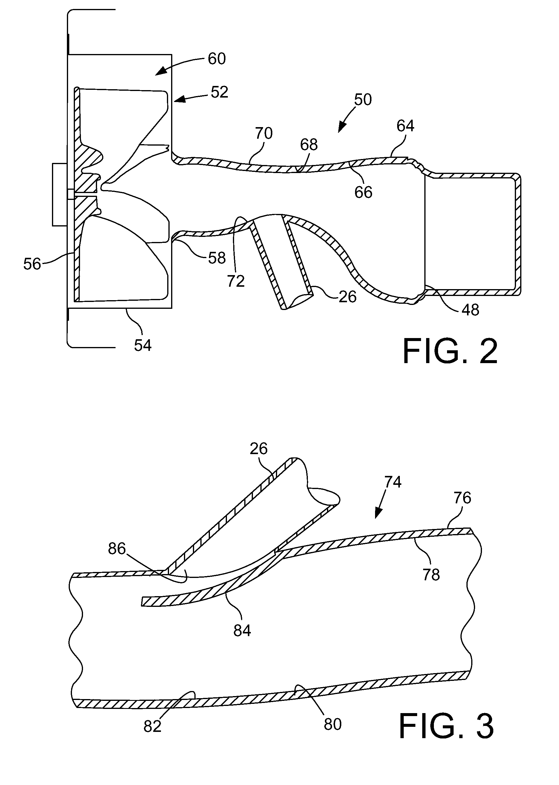
A work vehicle operating in a highly contaminated environment has a radiator with a rotary screen debris removal device upstream of the radiator. The debris thus removed passes through a fan for disposal away from the work machine. The engine is an air breathing fuel consuming engine and has a pre-cleaner for removing larger particles of air delivered to the engine for combustion. A conduit extends from the intake air pre-cleaner to a venturi device adjacent to and upstream of the fan for continuously and effectively removing particles from the engine air pre-cleaner.

Description

FIELD OF THE INVENTION[0001]The invention relates to a work machine and more specifically a work machine operating under highly contaminated conditions and to the removal of excess debris and particles from the air used to cool the work machine prime mover engine and to supply combustion air.BACKGROUND OF THE INVENTION[0002]The class of work machines utilized for agricultural, industrial and other uses termed as work machines typically operates in a highly contaminated environment, thus making the function of cleaning air used by an air breathing internal combustion engine especially important. Nowhere is this as important as in the agricultural field where the work machine is in a field harvesting crops which generates significant contaminants in the form of debris and particles. It is necessary for such machines to have a pre-cleaner since the ambient level of particles is so significant. An air filter alone would quickly become clogged. In the present environment, pre-cleaners ar...

Claims


Application Information

Patent Timeline
Patent Type & Authority Patents(United States)
IPC IPC(8): F01P11/12F01P5/02F28F19/01
CPCF02M35/02F02M35/086F02M35/164F02M35/06
Inventor VANDIKE, NATHAN R.SHEIDLER, ALAN D.
Owner DEERE & CO
Learn More