Apparatus for occluding body lumens

a technology for occluding body lumens and apparatuses, applied in the field of medical equipment, can solve the problems of film collapse or fold in a different manner, and achieve the effect of preventing accidental deployment of tension members and facilitating manual deploymen

Inactive Publication Date: 2011-02-01
TAKAI HOSPITAL SUPPLY
View PDF43 Cites 31 Cited by
  • Summary
  • Abstract
  • Description
  • Claims
  • Application Information

AI Technical Summary

Benefits of technology

[0011]The present apparatus provides an improved luminal occlusion device, comprising a tension member, an elongate shaft, and a flat film having an axial receptacle for receiving a distal portion of the tension member. The tension member has a proximal end and a distal end, and is typically formed as a solid core wire having the dimensions and properties generally associated with smaller guidewires, such as uretal guidewires. The elongate shaft serves as a guide structure for the tension member and will usually comprise a hollow tube, such as a hollow polymeric tubular body, having a distal end and a proximal end. The tension member is slidably received within a lumen of the elongate shaft, and the distal end of the tension member is able to extend distally from the distal end of the shaft and axially translate relative to the elongate shaft. The axial receptacle of the flat film will then be disposed over the tension member and will typically have a proximal end fixed or otherwise coupled to a distal end of the elongate shaft and a distal end fixed or otherwise coupled to a distal location on the tension member. Thus, the flat film can be axially elongated and placed in a low profile configuration by advancing the tension member distally relative to the elongate shaft. Conversely, the flat film can be compacted into a high volume configuration by proximally drawing the tension member relative to the elongate shaft. By having the axial receptacle of the film positioned over the tension member, the symmetry of the deployment is improved.
[0012]In particular embodiments of the present invention, the flat film has characteristics which are further selected to improve the symmetry and effectiveness of the deployment. For example, flat film will typically have parallel edges which are spaced apart by a distance in the range from 2 mm to 15 mm and will have a length in the axial direction in the range from 10 cm to 100 cm. Preferred flat films will comprise one or more polymeric sheet(s) having a total thickness in the range from 0.1 mm to 0.5 mm. It has been found that sheets with these characteristics will have a very low profile elongated configuration to facilitate introduction into the body lumen, particularly into ureters and past kidney stones, as well as having a deployed, high-volume configuration which is symmetric and particularly suitable for deployment and occlusion within a ureter.
[0018]The occlusion device will typically have a handle at or near its proximal end. In preferred embodiments, the handle is removably attachable to the proximal end of the elongate shaft and is positioned over a proximal end of the tension member. In such cases, the handle allows manipulation of the occlusion device while it is being introduced into the ureter or other body lumen. The handle also prevents accidental deployment of the tension member since it covers and protects the distal end. Thus, in use, the handle will be moved after the occlusion device has been positioned within the body lumen at its target location. After the handle is removed, the proximal end of the tension member is exposed so that the user may manually grasp the proximal end, and pull on it in a proximal direction in order to deploy the flat film. Usually, the proximal end of the tension member will be modified to provide a gripping surface to facilitate manual deployment.
[0019]In still further aspects of the present invention, the tension member may be modified or additional components provided in order to lock or hold the flat film in its deployed configuration after the tension member has been pulled proximally. For example, a detent structure may be formed at or near the proximal end of the tension member, where the detent expands when the tension member is proximally retracted to deploy the film. The expanded detent thus blocks or inhibits inadvertent distal movement of the tension member which would unintentionally return the flat film to its low profile configuration. The detent may comprise, for example, a bend in the tension member, such as a short serpentine section.

Problems solved by technology

In particular, the markers may be more rigid or stiff than the film, causing the film to collapse or fold in a manner different from what would occur without the marker.

Method used


Image

  • Apparatus for occluding body lumens
  • Apparatus for occluding body lumens
  • Apparatus for occluding body lumens

Examples


Embodiment Construction

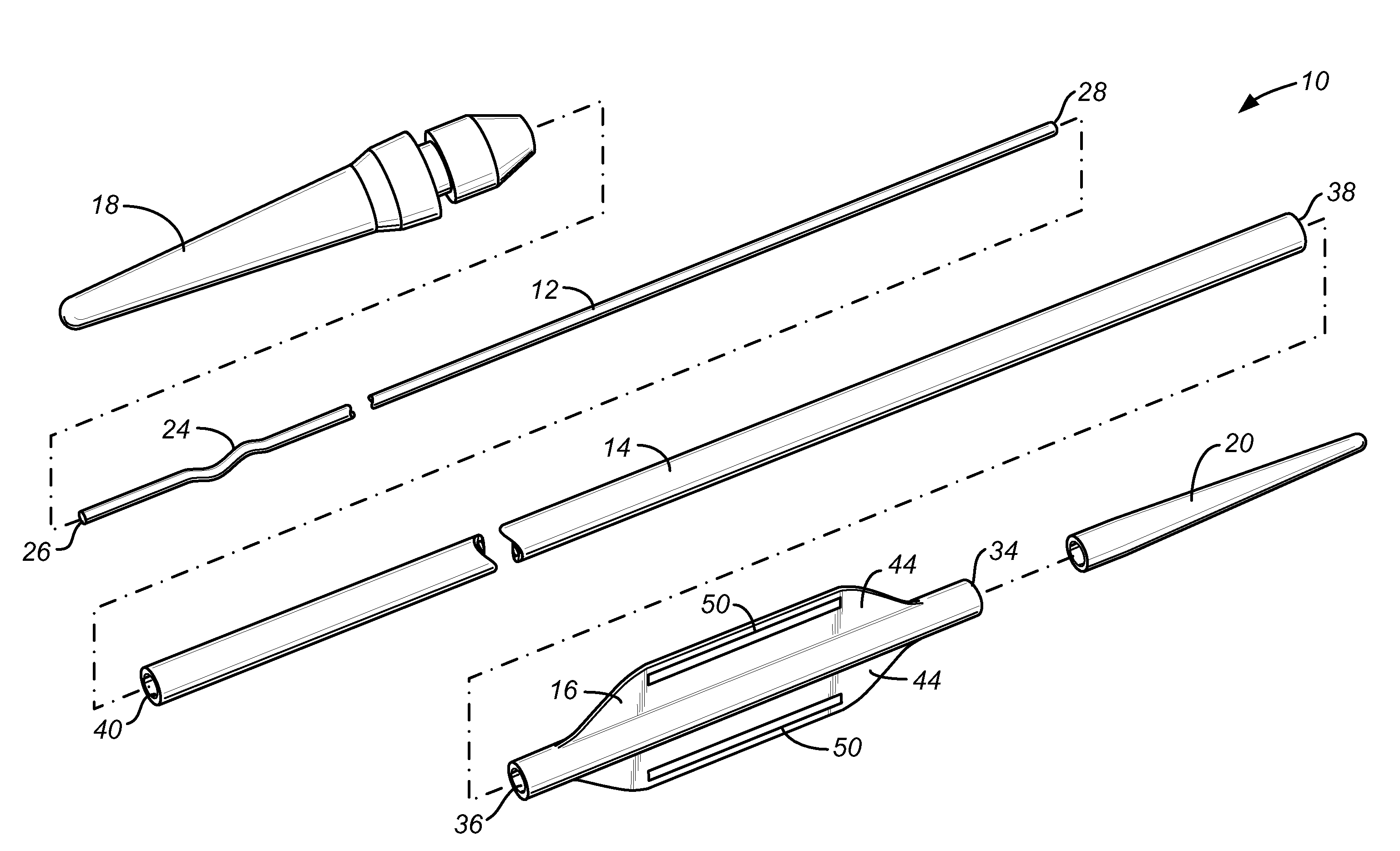
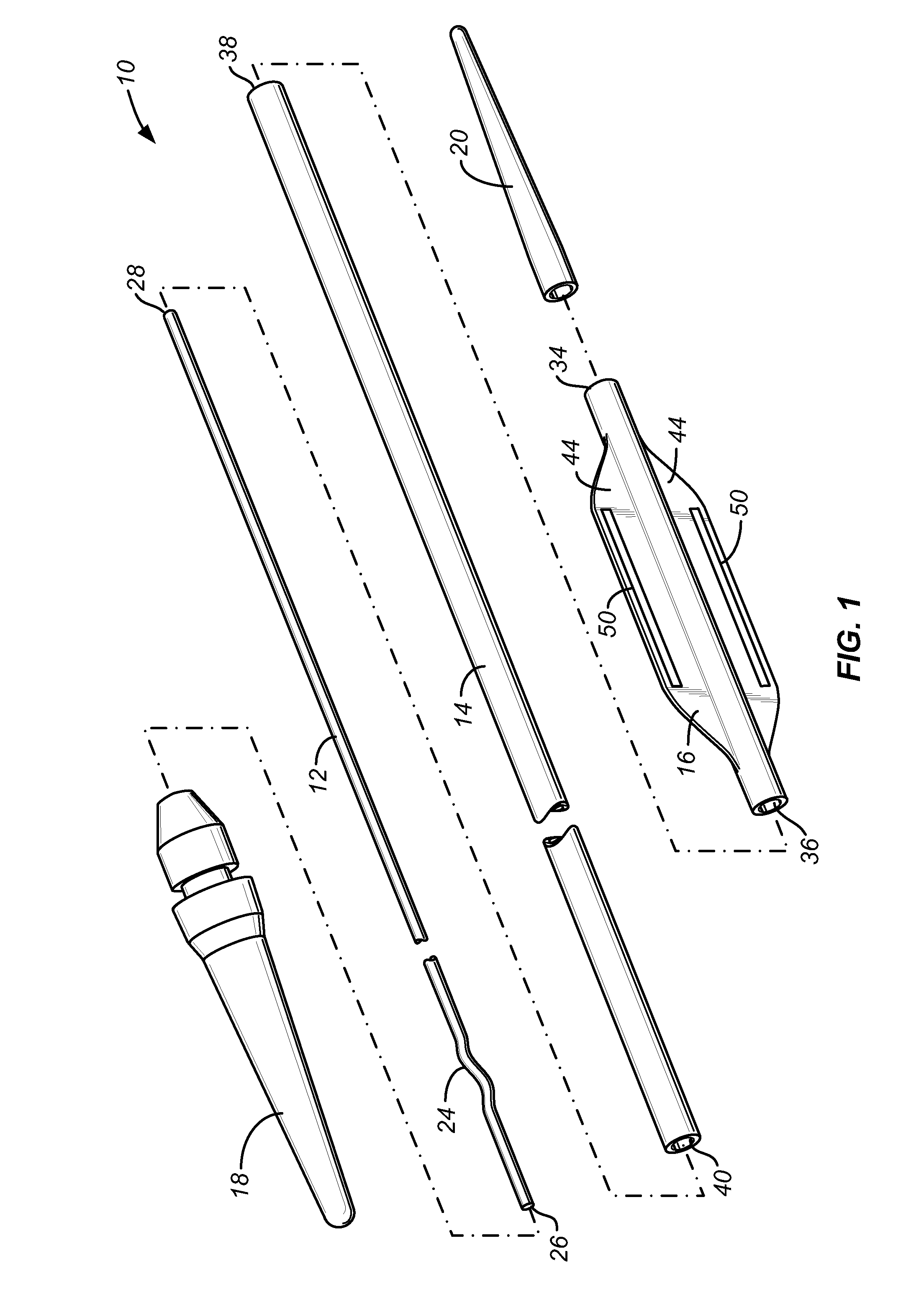
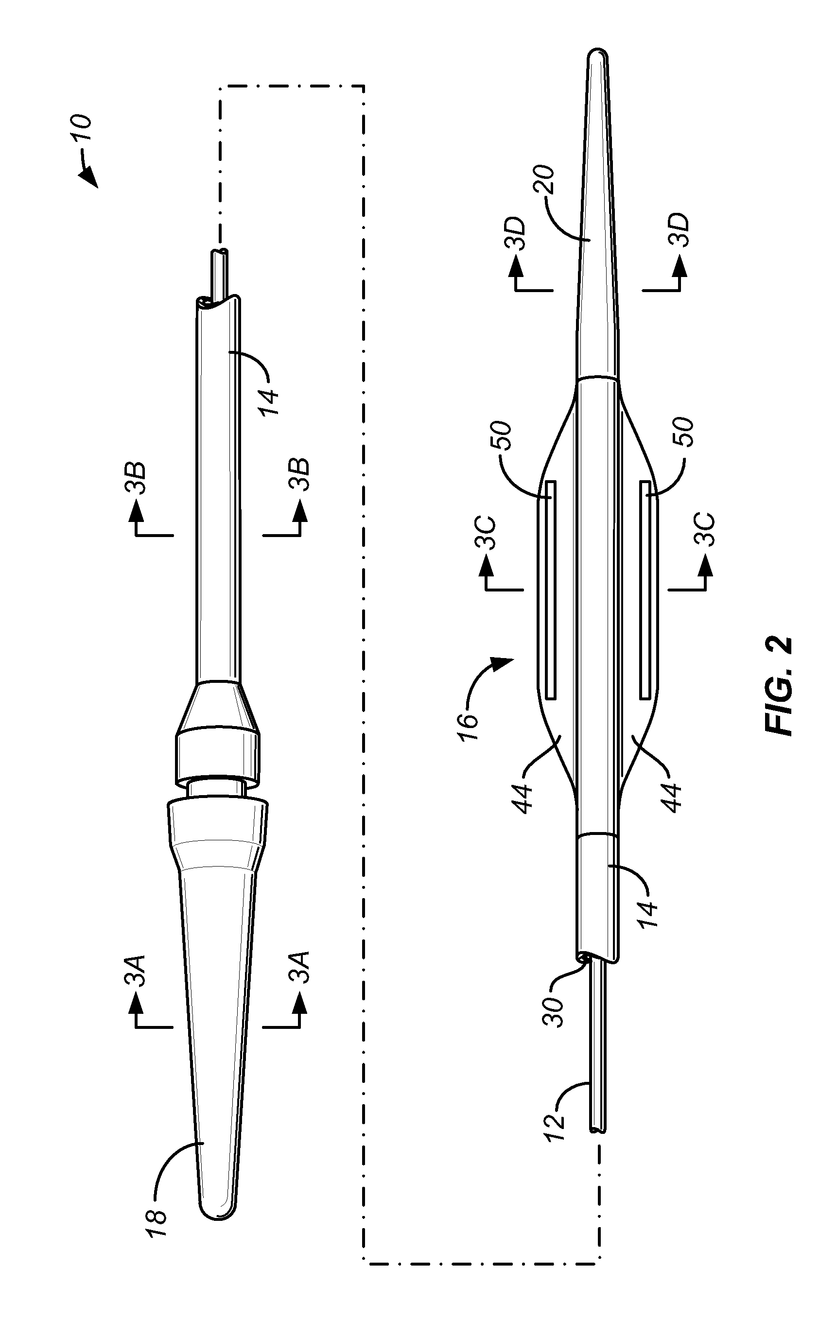
[0024]As illustrated in FIGS. 1, 2, and 3A-3D, an exemplary luminal occlusion device 10 constructed in accordance with the principles of the present invention, comprises a tension member 12, an elongate shaft 14, a flat film 16, a handle 18, and a distal tip 20. The tension member 12 comprises a solid core wire, typically composed of stainless steel or nickel-titanium alloy, having a length in the range set forth above. A serpentine detent 24 is formed near a proximal end 26 thereof. The distal end 28 of the tension member will pass through a lumen 30 of the elongate shaft 14, as best seen in FIGS. 2 and 3B. The distal end 28 is connected to a distal end 34 of the flat film 16, while a distal end 38 of the elongate shaft 14 is connected to a proximal end 36 of the flat film. The distal portion of the tension member 12 passes through an axial receptacle 42 of the flat film 16, as best seen in FIG. 3C, and proximal retraction of the tension member 12 relative to elongate shaft 14 will...


PUM


Abstract

A luminal occlusion device comprises a tension member, an elongate shaft, and a flat film having an axial receptacle which is received over a distal portion of the tension member. The flat film has proximal and distal ends which are attached to the distal ends of the tension member and the elongate shaft, respectively. Thus, distal advancement of the tension member relative to the shaft will cause the flat film to assume a low profile configuration, while proximal retraction of the tension member relative to the elongate shaft will cause the flat film to assume a foreshortened, compacted configuration. The film usually includes one or more radioopaque markers which help shape the compacted film.

Description

CROSS-REFERENCES TO RELATED APPLICATIONS[0001]The present application is related to but does not claim the benefit of copending application Ser. No. 10 / 886,886, filed on Jul. 7, 2004 and Ser. No. 11 / 777,515, filed on the same day as the present application, the full disclosures of which are incorporated herein by reference.BACKGROUND OF THE INVENTION[0002]1. Field of the Invention[0003]The present invention relates generally to medical apparatus. More particularly, the present invention relates to apparatus for treating ureters and other body lumens.[0004]It is common for kidney stones to pass from the kidney through the ureter to the urinary bladder. While muscular peristalsis of the ureter will often pass the stones into the bladder without complication, in some instances large and / or irregularly shaped stones may become lodged within the ureter causing discomfort and potential damage to the ureter and upper collective system.[0005]A number of ways have been proposed for dislodgin...

Claims


Application Information

Patent Timeline
Patent Type & Authority Patents(United States)
IPC IPC(8): A61M29/00
CPCA61B17/12022A61B17/12099A61B17/12131
Inventor DESAI, RUPESHHUANG, ALEXANDER L.YEE, STEVEN
Owner TAKAI HOSPITAL SUPPLY
Why Eureka
Try Eureka