Headphone amplifier circuit

a headphone amplifier and circuit technology, applied in the direction of amplifiers with semiconductor devices/discharge tubes, transducer casings/cabinets/supports, etc., can solve the problems of high emi (electromagnetic interference), difficult miniaturization of portable electronic devices, and low power efficiency

Active Publication Date: 2011-02-01
ANALOG DEVICES INC
View PDF10 Cites 13 Cited by
  • Summary
  • Abstract
  • Description
  • Claims
  • Application Information

AI Technical Summary

Problems solved by technology

Such large capacitors make miniaturizing portable electronic devices difficult.
Although large DC blocking capacitors are avoided, the amplifier circuit shown in FIG. 2 is a class AB amplifier, and has low power efficiency.
Another prior art approach is to use a class D amplifier, which has better power efficiency than a class AB amplifier, but high EMI (Electromagnetic interference), which can be a problem.

Method used


Image

  • Headphone amplifier circuit
  • Headphone amplifier circuit
  • Headphone amplifier circuit

Examples


Embodiment Construction

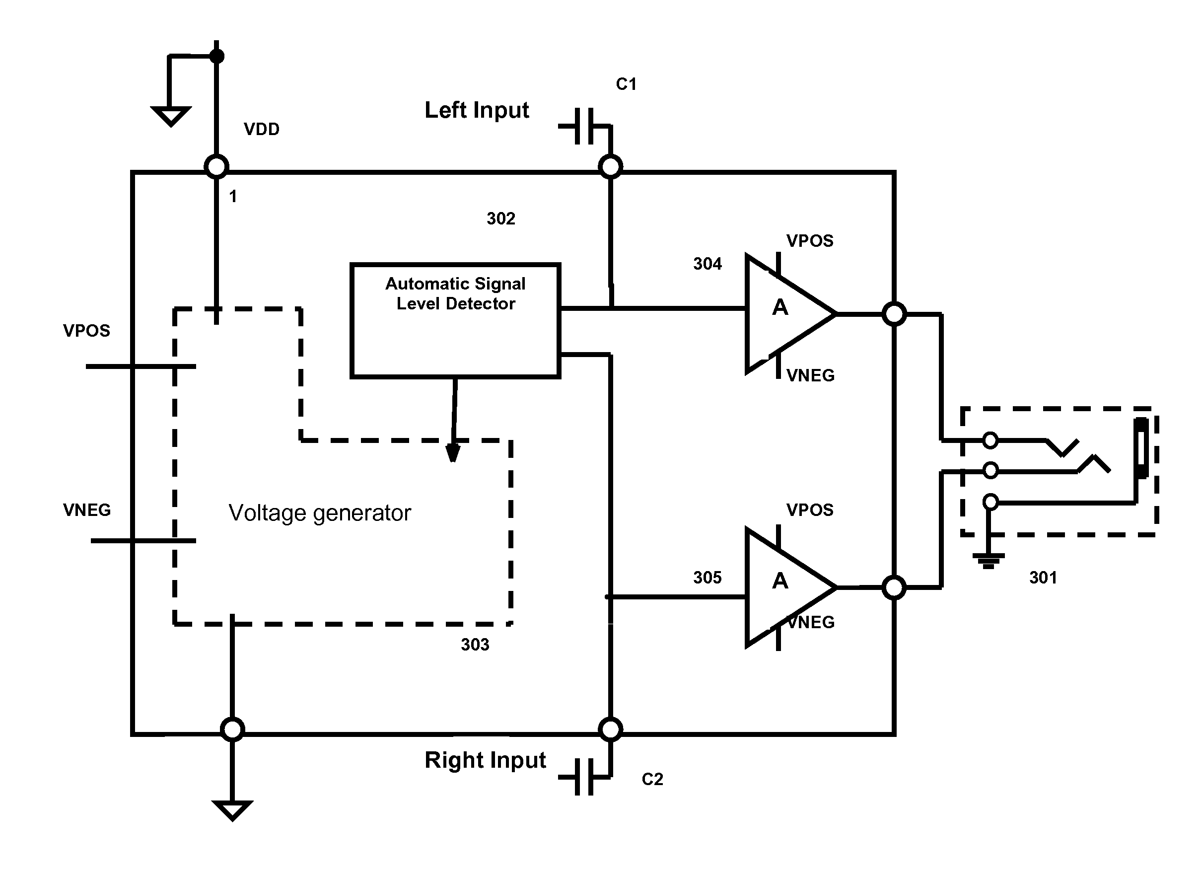
[0021]Embodiments of the present invention provide a class G headphone amplifier circuit which has improved power efficiency and low EMI. Embodiments may use an automatic signal level detector to detect the signal level of incoming signals and dynamically adjust positive and negative power supplies for headphone amplifiers. A voltage generator may generate pairs of differential output voltages at variable amplitudes, and supply to headphone amplifiers an amplitude determined by the automatic signal level detector. As a result, headphone amplifiers receive power supplies at voltage levels that correspond to an input signal level which may improve power efficiency and avoid signal clipping.

[0022]FIG. 3 illustrates a headphone amplifier circuit according to one embodiment of the present invention. The circuit 300 may include an automatic signal level detector 302, a voltage generator 303 and a pair of amplifiers 304, 305. The level detector 302 may compare input signals, which are to b...


PUM


Abstract

A class G headphone amplifier circuit with improved power efficiency and low EMI. It may use an automatic signal level detector to detect the signal level of incoming signals and determine positive and negative power supplies for headphone amplifiers accordingly. A voltage generator may generate pairs of differential output voltages at a plurality of amplitude steps, and supply to headphone amplifiers the pair with the amplitude determined by the automatic signal level detector. As a result, headphone amplifiers are biased according to the input signal level, and the multiple voltage rails may improve power efficiency and avoid clipping.

Description

BACKGROUND INFORMATION[0001]The present invention relates generally to amplifier circuits and more specifically to headphone amplifier circuits in portable electronic devices.[0002]In portable electronic devices, such as portable CD players and MP3 players, audio signals are amplified by headphone amplifiers. A headphone amplifier is typically externally biased by two power supplies to accurately represent incoming signals. However, portable electronic devices usually use a single power supply, e.g., a battery, as the only source of power. In a prior art headphone amplifier circuit shown in FIG. 1, headphone amplifiers 101 and 102 have their positive power supply terminals coupled to a positive power supply VDD and their negative power supply terminals coupled to ground, and consequently are biased at mid-rail (VDD / 2). Since the output of the amplifiers 101 and 102 are at a higher DC voltage with respect to ground, relatively large capacitors 103 and 104 are required to prevent high...

Claims


Application Information

Patent Timeline
Patent Type & Authority Patents(United States)
IPC IPC(8): H03F3/04
CPCH03F1/025H03F3/21H03F3/3081H03F2200/03H03F2200/507H03F2200/511H03F2200/516H03F2203/21196H03F2203/30072
Inventor YE, JINGHUASHEN, HUILI, DANNY
Owner ANALOG DEVICES INC
Why Eureka
Try Eureka