
Removable antennas for electronic devices

a technology for electronic devices and antennas, applied in the direction of collapsible antennas, quick-release antenna elements, coupling device connections, etc., can solve the problems of external antenna designs that protrude excessively from the device housing, external antenna designs that are not considered practical in electronic devices with conductive cases, and may be susceptible to damage, so as to achieve the effect of preventing damag

Active Publication Date: 2011-02-01
APPLE INC
View PDF7 Cites 13 Cited by
  • Summary
  • Abstract
  • Description
  • Claims
  • Application Information

AI Technical Summary

Benefits of technology

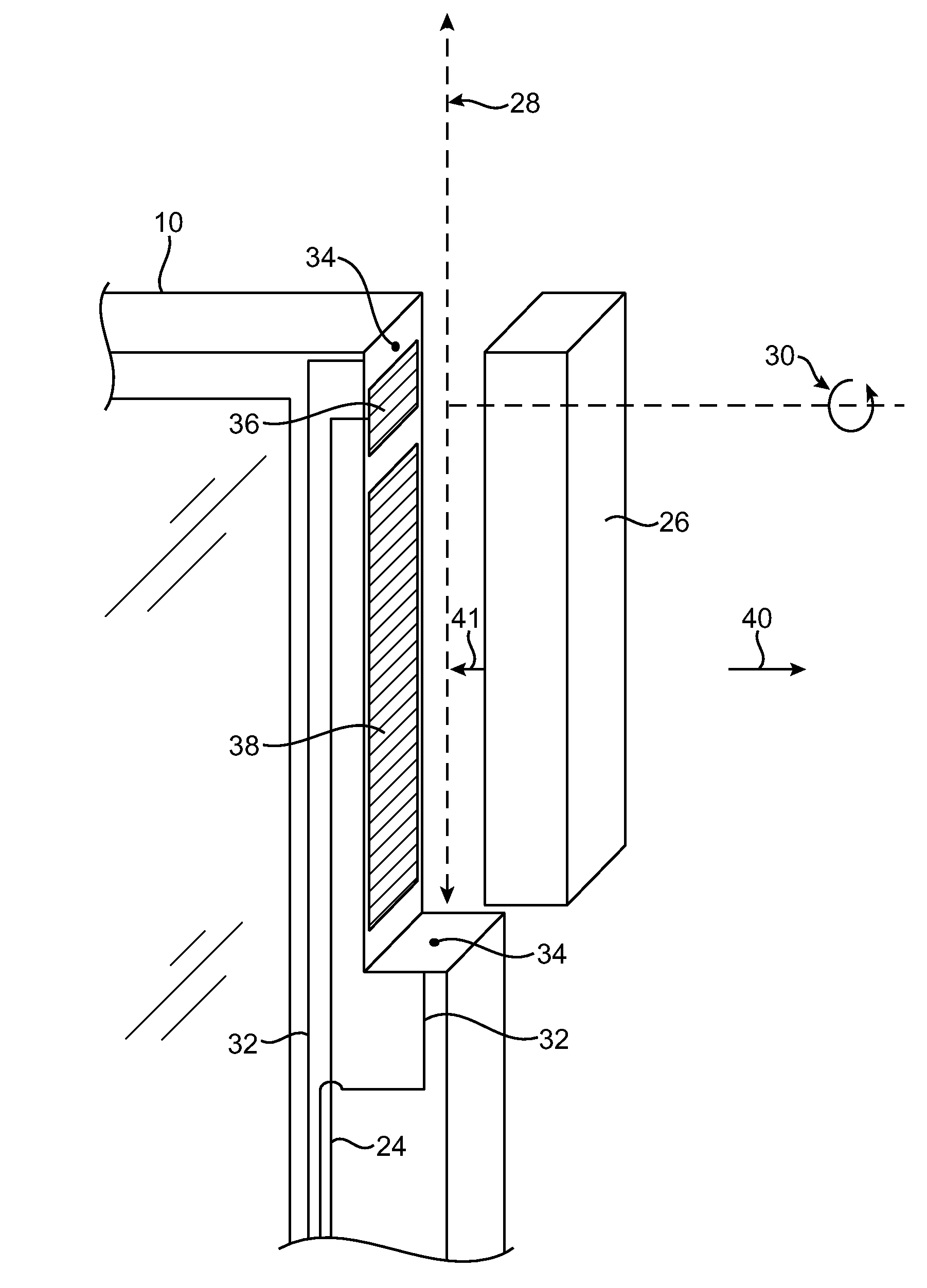
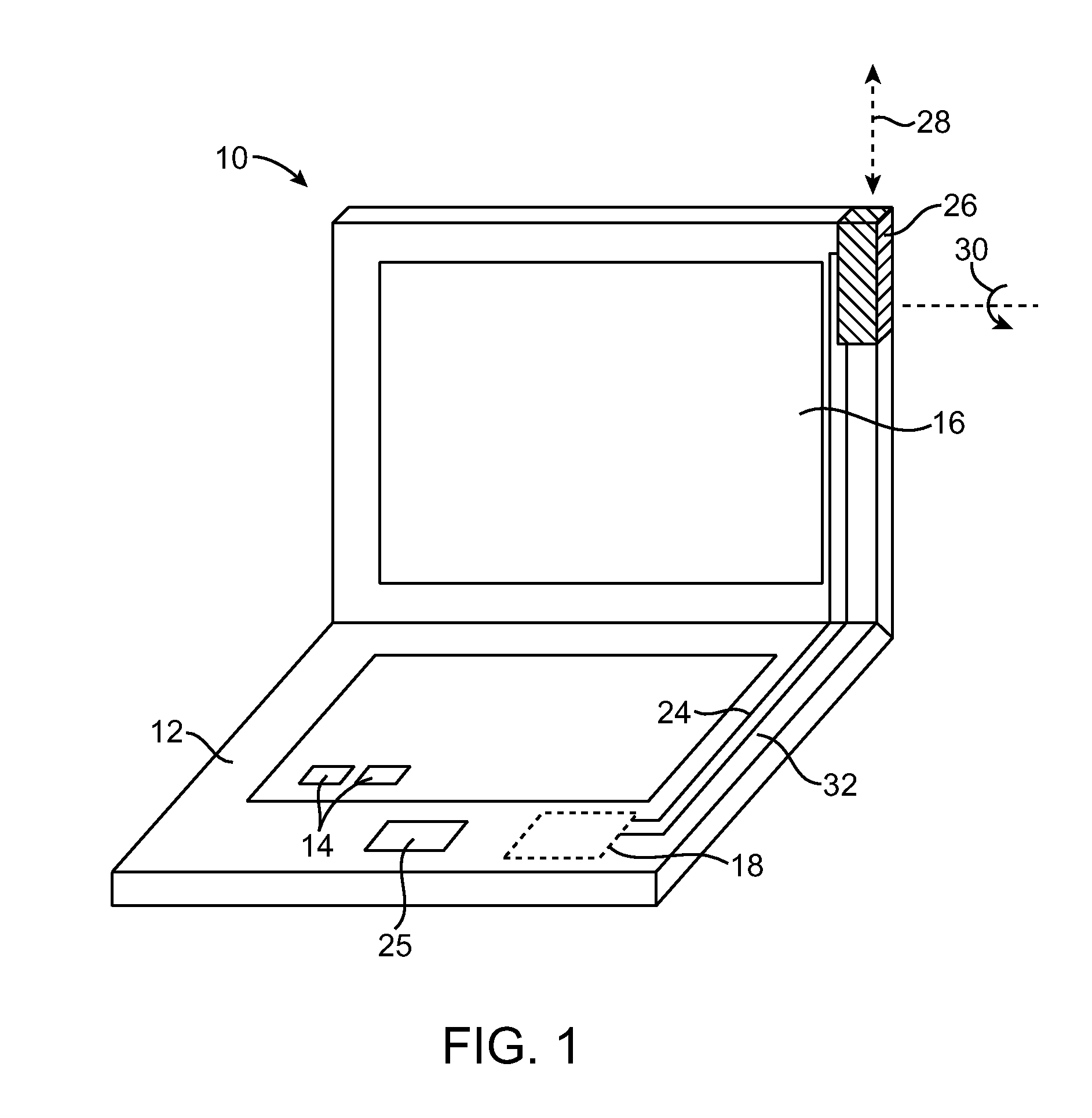
[0005]In accordance with an embodiment of the present invention, removable antennas for electronic devices are provided. A removable antenna may be magnetically coupled to an electronic device. The antenna and the electronic device may have corresponding coupling structures. The coupling structures may be magnetic and / or ferromagnetic and may be integrated into the structure of the antenna and the structure of the electronic device. The coupling structures may provide a magnetic force that magnetically couples the antenna to the electronic device. With one suitable arrangement, the coupling structures may be formed in distinct portions of the antenna and the electronic device. Because the antenna is magnetically coupled to the electronic device, the antenna may be removed from the electronic device without damaging the antenna, the electronic device, or the coupling structures. This helps to prevent damage in the event that the antenna is accidently dislodged.
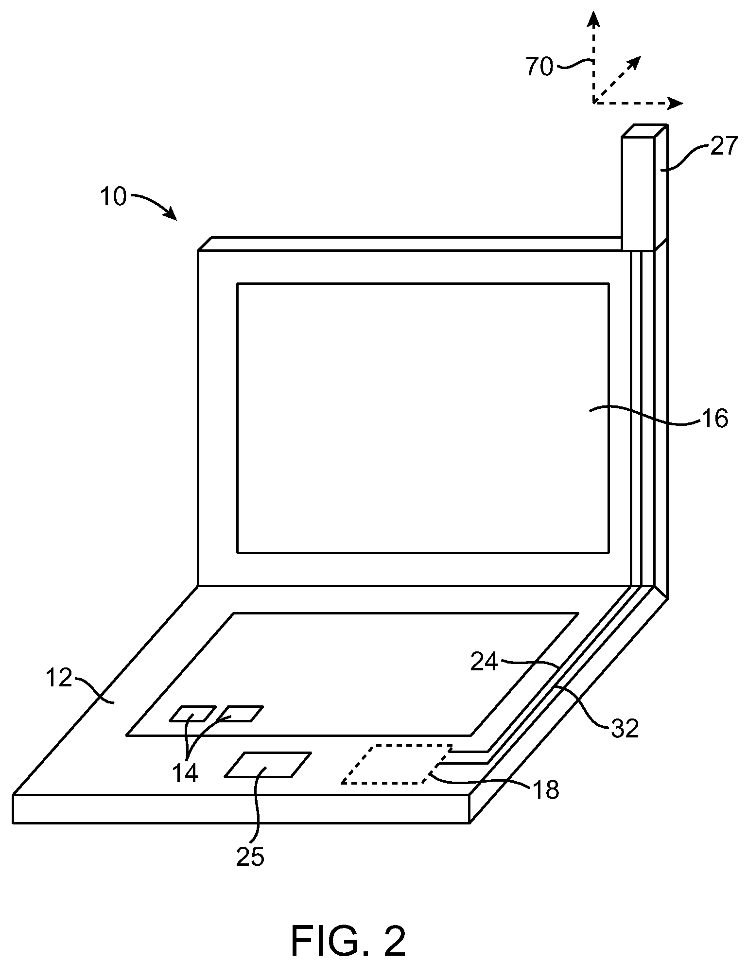
[0006]The antenna need not be extendable. In embodiments where the antenna is not extendable, the coupling structures on the electronic device may be configured to blend in with surrounding portions of the electronic device. Non-extendable removable antenna arrangements may allow a user of the electronic device to easily swap antennas of varying shapes and sizes.
[0007]If desired, the antenna may be extendable. The electronic device may have a conductive housing. The antenna may have improved transmission and reception efficiencies when the antenna is placed in an extended position away from the conductive housing. In the antenna's extended position, the antenna's performance may be enhanced by the increase in separation (e.g., compared to a stowed position) between an antenna resonating element in the antenna and the ground plane of the metal housing of the electronic device. The antenna resonating element in the antenna may be formed from any suitable antenna design. For example, the antenna resonating element may be formed from a flex circuit containing a strip of conductor, a piece of stamped metal foil, a length of wire, etc.
[0008]In addition to physically coupling the antenna and the electronic device together, the coupling structures may couple the antenna resonating element structures in the antenna to a transceiver in the electronic device through a communications path. The coupling of the antenna resonating element to the communications path may be magnetic, so that no damage will result when the coupling structures are separated. The coupling structures may be also conductive. Conductive coupling structures may be used to electrically connect the communications path and the antenna resonating element while physically attracting the antenna to the electronic device using the magnetic properties of the coupling structures.
[0011]Coupling structures may provide a magnetic force that helps guide an antenna from its stowed position to its extended position. For example, in embodiments in which the antenna is configured to extend or retract by reciprocating along its length, the coupling structures may help to guide the antenna in a straight line along the length of the antenna.

Problems solved by technology

This poses challenges when designing an antenna for an electronic device with this type of housing.
An internal antenna would be shielded by a high-conductivity housing, so internal antenna designs are often not considered practical in electronic devices with conductive cases.
On the other hand, external antenna designs that protrude excessively from a device housing may have an unattractive appearance.
External antenna designs may also be susceptible to damage.

Method used


Image

  • Removable antennas for electronic devices
  • Removable antennas for electronic devices
  • Removable antennas for electronic devices

Examples


Embodiment Construction

[0038]The present invention relates generally to antennas, and more particularly, to removable antennas for wireless electronic devices.

[0039]The wireless electronic devices may be any suitable electronic devices. As an example, the wireless electronic devices may be desktop computers or other computer equipment. The wireless electronic devices may also be portable electronic devices such as laptop computers or small portable computers of the type that are sometimes referred to as ultraportables. With one suitable arrangement, the portable electronic devices may be handheld electronic devices.

[0040]Examples of portable and handheld electronic devices include cellular telephones, media players with wireless communications capabilities, handheld computers (also sometimes called personal digital assistants), remote controls, global positioning system (GPS) devices, and handheld gaming devices. The devices may also be hybrid devices that combine the functionality of multiple conventiona...


PUM


Abstract

A removable antenna is provided for an electronic device such as a laptop computer. An antenna resonating element is mounted within the antenna. Magnetic coupling structures are used to magnetically attach the antenna to the electronic device. The magnetic coupling structures couple the antenna resonating element to circuitry in the electronic device. The electronic device may have an antenna receptacle that holds the antenna in a stowed position and allows the antenna to extend to an extended position. A user may extend the antenna by sliding the antenna or by rotating the antenna to its extended position. The coupling structures may allow the antenna to break away from the electronic device without damage.

Description

BACKGROUND[0001]This invention relates to antennas, and more particularly, to removable antennas for electronic devices.[0002]It may be desirable to include wireless communications capabilities in an electronic device. Electronic devices may use wireless communications to communicate with wireless base stations. For example, electronic devices may communicate using the Wi-Fi® (IEEE 802.11) bands at 2.4 GHz and 5.0 GHz and the Bluetooth® band at 2.4 GHz. Electronic devices may also use other types of communications links. For example, electronic devices such as cellular telephones may communicate using cellular telephone bands at 850 MHz, 900 MHz, 1800 MHz, and 1900 MHz (e.g., the main Global System for Mobile Communications or GSM cellular telephone bands). Communications are also possible in data service bands such as the 3G data communications band at 2100 MHz (commonly referred to as UMTS or Universal Mobile Telecommunications System).[0003]Many popular housing materials such as ...

Claims


Application Information

Patent Timeline
IPC IPC(8): H01Q1/24
CPCH01Q1/084H01Q1/088H01Q1/12H01Q1/2258H01R13/6205H01R2201/02
Inventor DEGNER, BRETT WILLIAMLIGTENBERG, CHRISANDRE, BARTLEY K.KOUGH, DOUGLAS BLAKE
Owner APPLE INC
Learn More