Loop type heat dissipating apparatus with sprayer

a heat dissipating apparatus and loop technology, applied in the field of loop heat dissipation apparatus, can solve the problems of disadvantaged heat pipe b>10/b> using a wick structure, inability to meet the increasingly strict requirements for heat dissipation, and limited maximum amount of heat transferred, etc., to achieve short heat transfer distance, small contact surface area, and less thermal resistance

Inactive Publication Date: 2011-02-08
IND TECH RES INST
View PDF25 Cites 5 Cited by
  • Summary
  • Abstract
  • Description
  • Claims
  • Application Information

AI Technical Summary

Benefits of technology

[0015]In light of the aforesaid drawbacks of the prior art, it is a primary objective of the present invention to provide a loop type heat dissipating apparatus with a sprayer so as to enhance efficiency of heat dissipation.
[0016]Another objective of the present invention is to provide a loop type heat dissipating apparatus with a sprayer so as to reduce thermal resistance.
[0017]Yet another objective of the present invention is to provide a loop type heat dissipating apparatus with a sprayer so as to minimize accumulation of a working fluid at the bottom of the evaporator.
[0023]Compared to the prior art, the present invention discloses a loop type heat dissipating apparatus with a sprayer. The sprayer turns the liquid phase of the working fluid into microdroplets and ejects microdroplets to the heat source, such that no liquid film is formed at the bottom of the evaporator. Hence, a loop type heat dissipating apparatus with a sprayer disclosed by the present invention has less thermal resistance but is more efficient than a conventional loop heat pipe. The evaporator of the present invention is panel-shaped and thereby comes into contact with the heat source via a relatively large contact surface. The layout of both the first channel and the second channel of the present invention may be designed in light of the space available, so as to overcome the drawbacks of the prior art, namely short distance of heat transfer, and small contact surface area. In the present invention, the sprayer integrated into the evaporator has a pumping function embodying two merits. First, heat is dissipated more efficiently by spray cooling. Second, products are miniaturized, as the present invention functions well without a pump while the prior art uses a pump.
[0024]Accordingly, the loop type heat dissipating apparatus of the present invention increases heat dissipation efficiency, reduces thermal resistance, prevents accumulation of a working fluid at the bottom of the evaporator, achieves miniaturization, and enhances industrial applicability, thus solving the problems posed by the prior art.

Problems solved by technology

Nevertheless, the performance of a conventional cooler equipped with a heat spreader is subject to the thermal conductivity of a constituent material and thereby achieves only passive cooling, thus being unfit to meet the increasingly strict requirements for heat dissipation.
However, in so doing, thermal resistance increases and thereby limits the maximum quantity of heat transferred.
In addition, the heat pipe 10 using a wick structure 109 is disadvantaged due to great flow resistance and thereby unfit to deal with great heat flux.
Last but not least, a conventional heat pipe has drawbacks, such as short heat transfer distance and small contact surface area.
Nonetheless, a droplet cooling device based on spray cooling requires an external pump to expel droplets out of micro-orifices, which increases the overall volume inevitably and therefore fails to meet the requirements for product miniaturization.
Accordingly, an issue that needs an urgent solution is related to endeavors to overcome the aforesaid drawbacks of the prior art.

Method used


Image

  • Loop type heat dissipating apparatus with sprayer
  • Loop type heat dissipating apparatus with sprayer
  • Loop type heat dissipating apparatus with sprayer

Examples


first embodiment

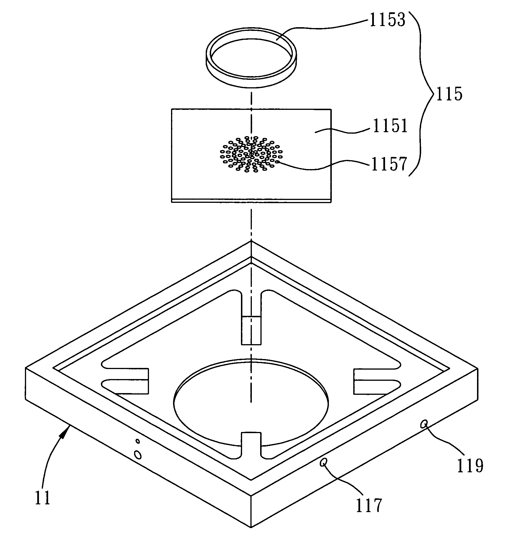
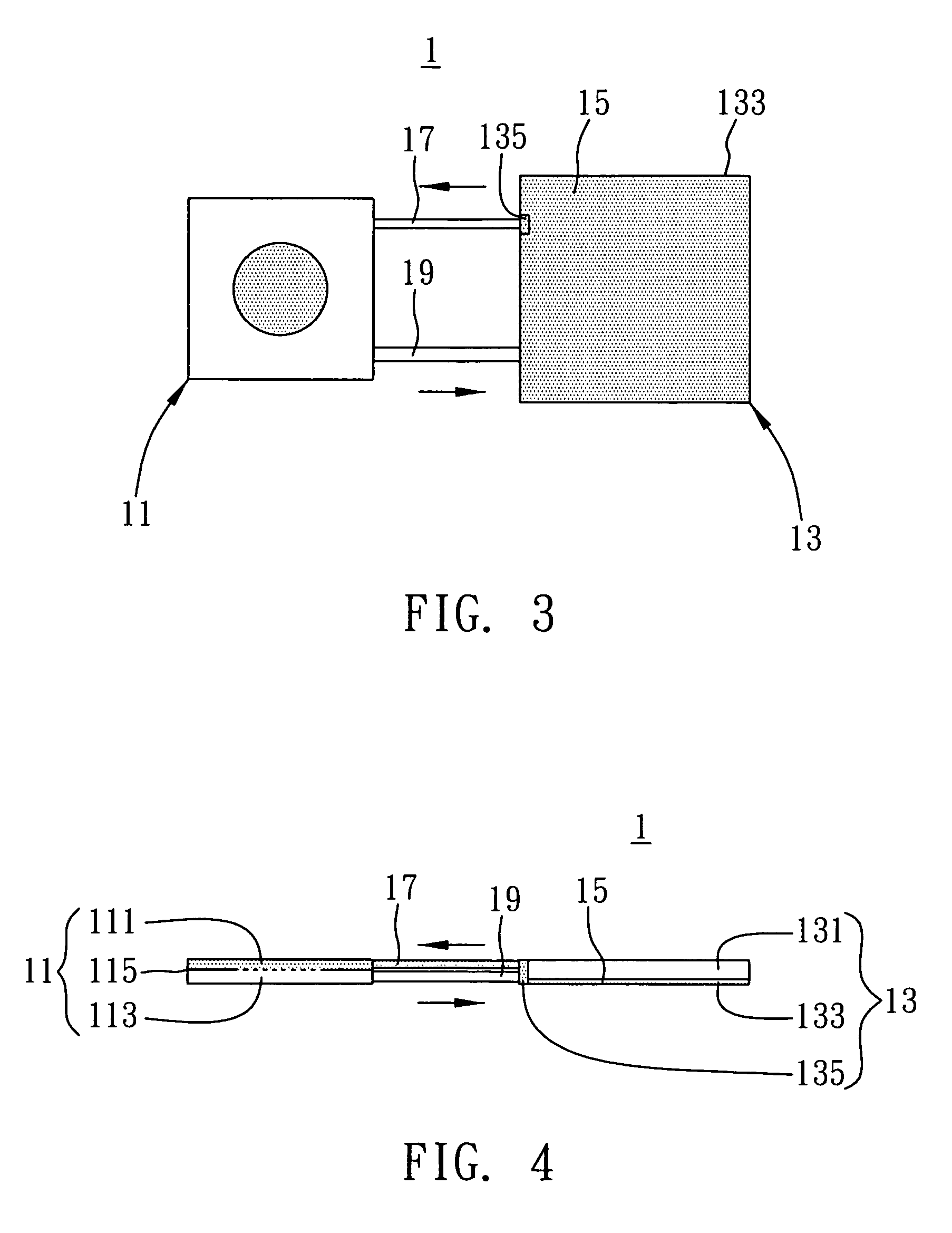
[0034]FIGS. 3 to 6B are drawings drawn according to the first embodiment of a loop type heat dissipating apparatus with a sprayer of the present invention.

[0035]Referring to FIG. 3 which is a schematic view showing a loop type heat dissipating apparatus 1 with a sprayer of the present invention. As shown in the drawing, the loop type heat dissipating apparatus 1 is applicable to heat transfer between a heat source and a heat sink (neither is shown). The loop type heat dissipating apparatus 1 comprises an evaporator 11, a condenser 13 communicating with the evaporator 11, and a working fluid 15 flowing between the evaporator 11 and the condenser 13. Connected between the evaporator 11 and the condenser 13 are a first channel 17 and a second channel 19. Although in this embodiment the evaporator 11 and the condenser 13 are connected by both the first channel 17 and the second channel 19, a means to connection is not limited to this embodiment and what are disclosed in the accompanying...

second embodiment

[0048]FIGS. 7 and 8 are schematic views showing a loop type heat dissipating apparatus with a sprayer of the second embodiment in accordance with the present invention. The drawings use the same or similar denotations for any second embodiment components the same as or similar to the corresponding first embodiment components, and the description is concise,

[0049]This embodiment markedly differs from the first embodiment in that the first channel and the second channel are parallel in the first embodiment but crossed in the second embodiment.

[0050]As shown in FIGS. 7 and 8, not only are the first channel 17 and the second channel 19 crossed, but the first channel 17 is directly connected to the wick structure 133, and thus the wick structure 135 of the first embodiment is spared.

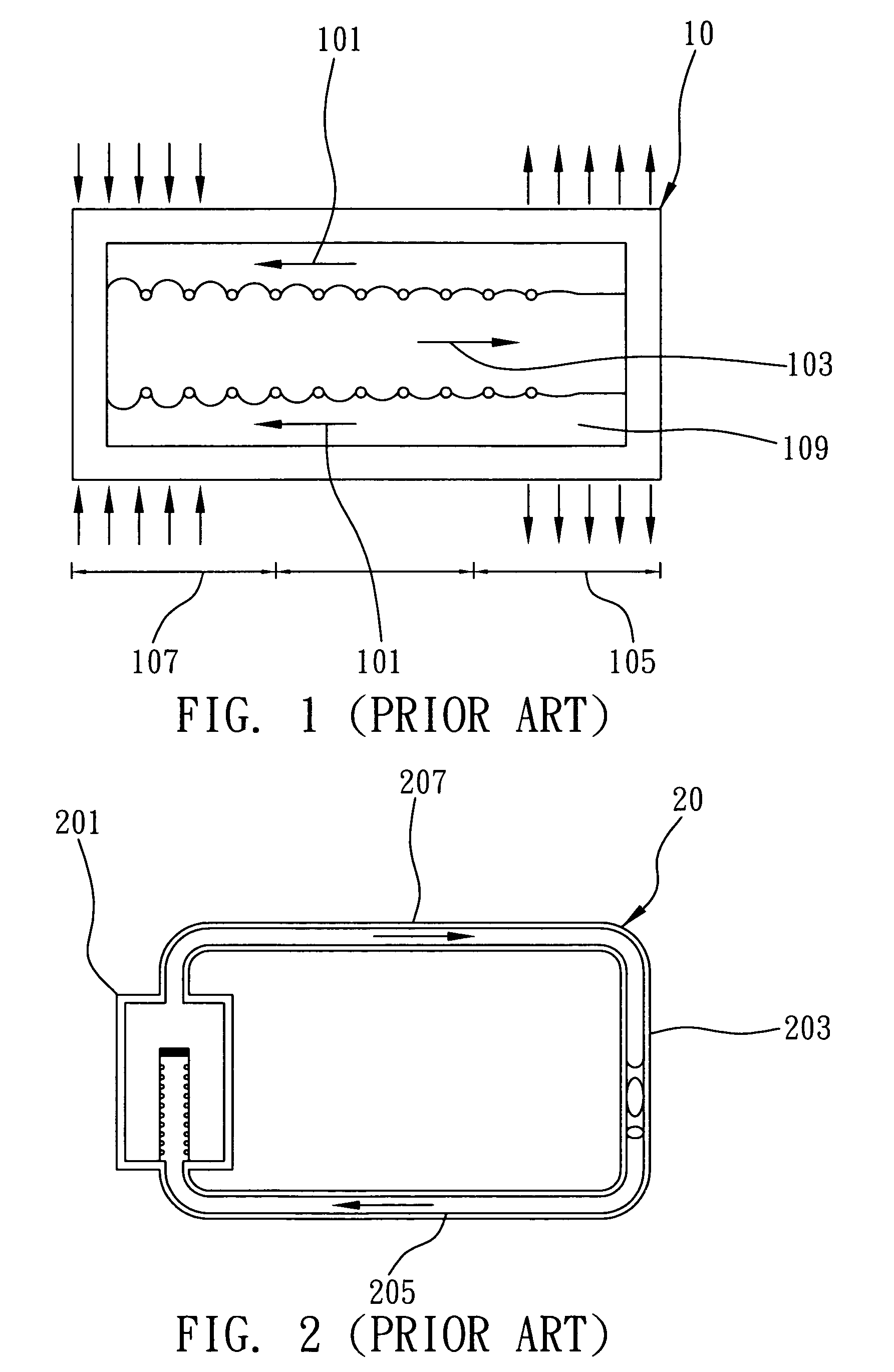
[0051]Unlike the prior art, this embodiment involves using a sprayer to dissipate the heat of a heat source by spray cooling, so as to increase the efficiency of heat dissipation and prevent the liquid phase ...


PUM


Abstract

A loop type heat dissipating apparatus with a sprayer for transferring heat between a heat source and a heat sink includes an evaporator, a condenser, and a working fluid. The evaporator contacts the heat source and includes a first chamber, a second chamber, and a sprayer disposed between therebetween. The condenser contacts the heat sink and includes a third chamber communicating with the second chamber and a wick structure disposed on one side of the third chamber. The working fluid fills the loop type heat dissipating apparatus and is turned into microdroplets via a sprayer. The sprayer impinges the microdroplets into the second chamber where the microdroplets are then evaporated by the heat source before proceeding to the third chamber for condensation, liquefaction and adhering to the wick structure. Eventually, the working fluid flows back to the first chamber under a pumping force actuated by the sprayer and completes the cycle.

Description

BACKGROUND OF THE INVENTION[0001]1. Field of the Invention[0002]The present invention relates to heat dissipation techniques, and more particularly, to a loop type heat dissipating apparatus for use with an active cooling technique.[0003]2. Description of the Prior Art[0004]As the electronic and information industries continue to develop, people nowadays have visions of owning electronic products which are multi-function, fast at computation and miniaturized. Manufacturers make efforts to enhance the performance of electronic products, thus producing electronic products which are more and more power-consuming. What the manufacturers are also multiplying is the heat flux of a heat source inside the electronic products produced, such as a CPU, laser diode, LED array, and multi-chip module (MCM). Hence, great importance is attached to rapid heat transfer across tiny space inside an electronic product.[0005]Taking a CPU as an example, existing designs of heat dissipations are, namely a ...

Claims


Application Information

Patent Timeline
Patent Type & Authority Patents(United States)
IPC IPC(8): F28D15/00
CPCF28D15/0266F28D15/043F28F13/00H01L23/427H01L23/4735H01L2924/3011Y10S165/908F28F2250/08H01L2924/0002H01L2924/00
Inventor WU, SHIH-KUOCHIEN, KUO-HSIANGYANG, JINN-CHERNGHUANG, CHI-MING
Owner IND TECH RES INST
Why Eureka
Try Eureka