Centrifugal blower

a centrifugal blower and centrifugal technology, which is applied in the direction of liquid fuel engines, vessel construction, marine propulsion, etc., can solve the problems of inability to obtain significant backflow prevention effects, unstable operation of centrifugal blowers, and noise generation, so as to reduce disturbance in airflow, noise reduction, disturbance

Inactive Publication Date: 2011-02-08
MITSUBISHI HEAVY IND LTD
View PDF26 Cites 38 Cited by
  • Summary
  • Abstract
  • Description
  • Claims
  • Application Information

AI Technical Summary

Benefits of technology

[0014]In consideration of the above circumstances, an object of the present invention is to provide a centrifugal blower with reduced noise.
[0045]According to the centrifugal blower according to the present invention, since backflow is prevented, noise is significantly reduced compared to the conventional centrifugal blower and it is unlikely to cause discomfort to a user, while operation can be carried out stably to perform excellent blowing.

Problems solved by technology

Since this backflow interferes with the flow of the air that has been taken into the casing from the bell-mouth (hereinafter, this flow is referred to as the “main flow”), noise is generated and operation of the centrifugal blower becomes unstable.
However, even by employing such a configuration a significant backflow prevention effect could not be obtained.
When operating a blower in such an area, the impeller stalls, airflow within the casing becomes unstable, and noise level increases.

Method used


Image

  • Centrifugal blower
  • Centrifugal blower
  • Centrifugal blower

Examples


first embodiment

[0056]A first embodiment of the present invention is described below, with reference to FIG. 1 through FIG. 3.

[0057]A centrifugal blower 1 according to the present embodiment is used as a blower of a vehicle air conditioner.

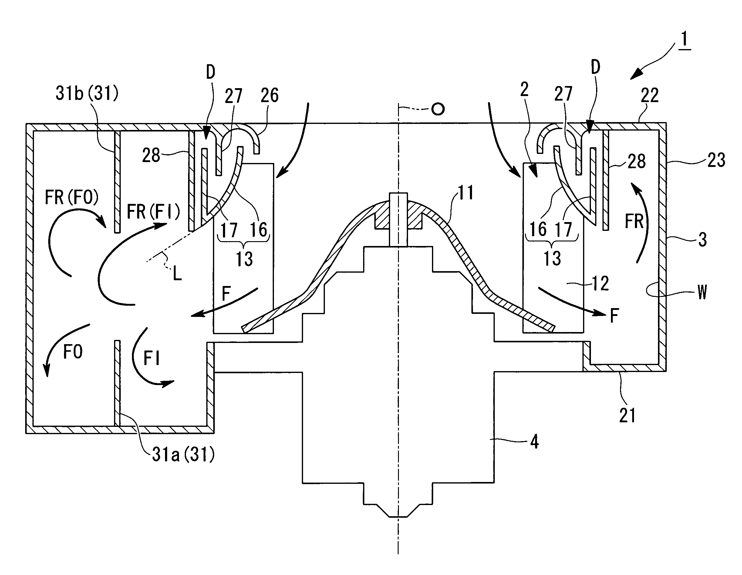
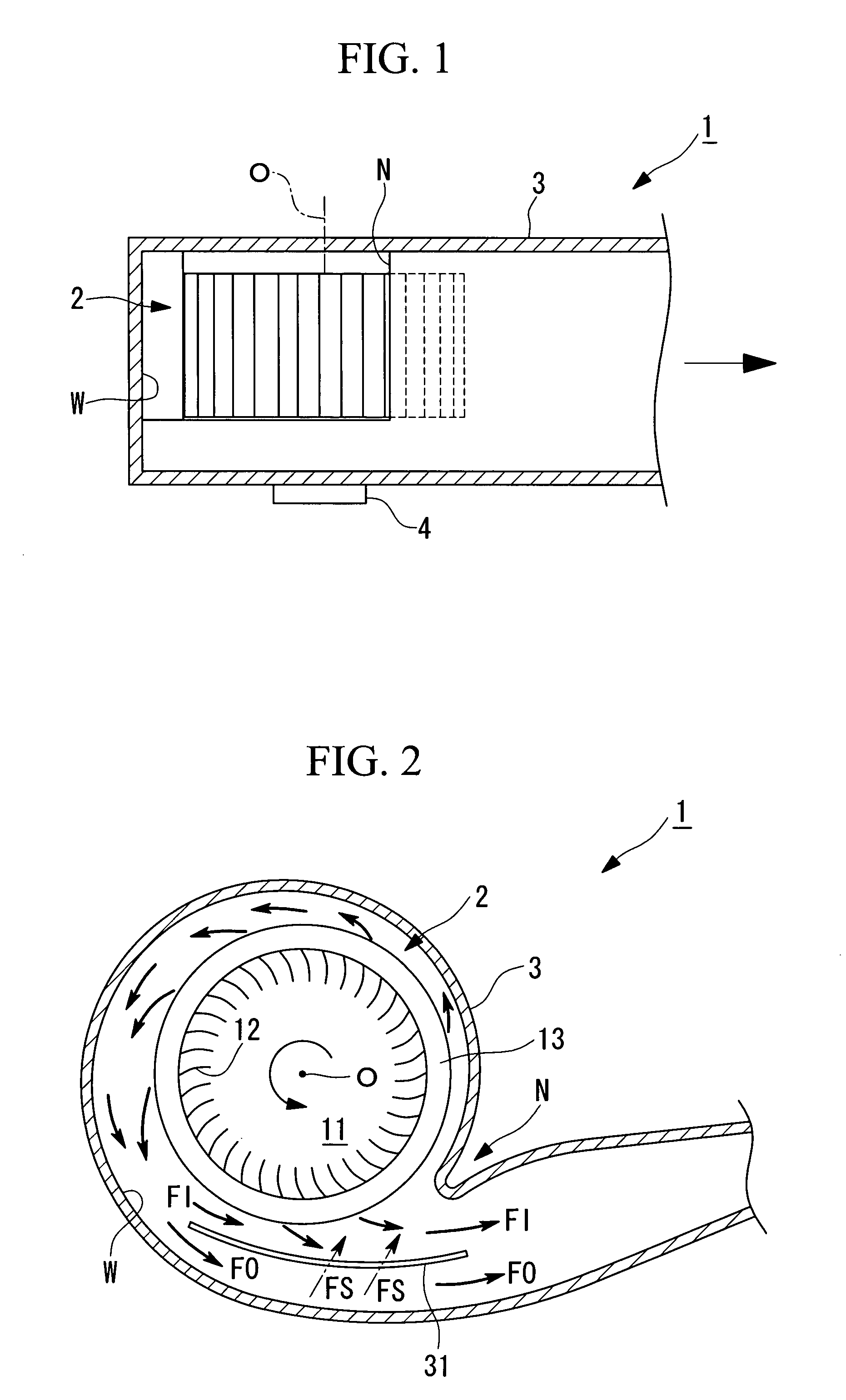
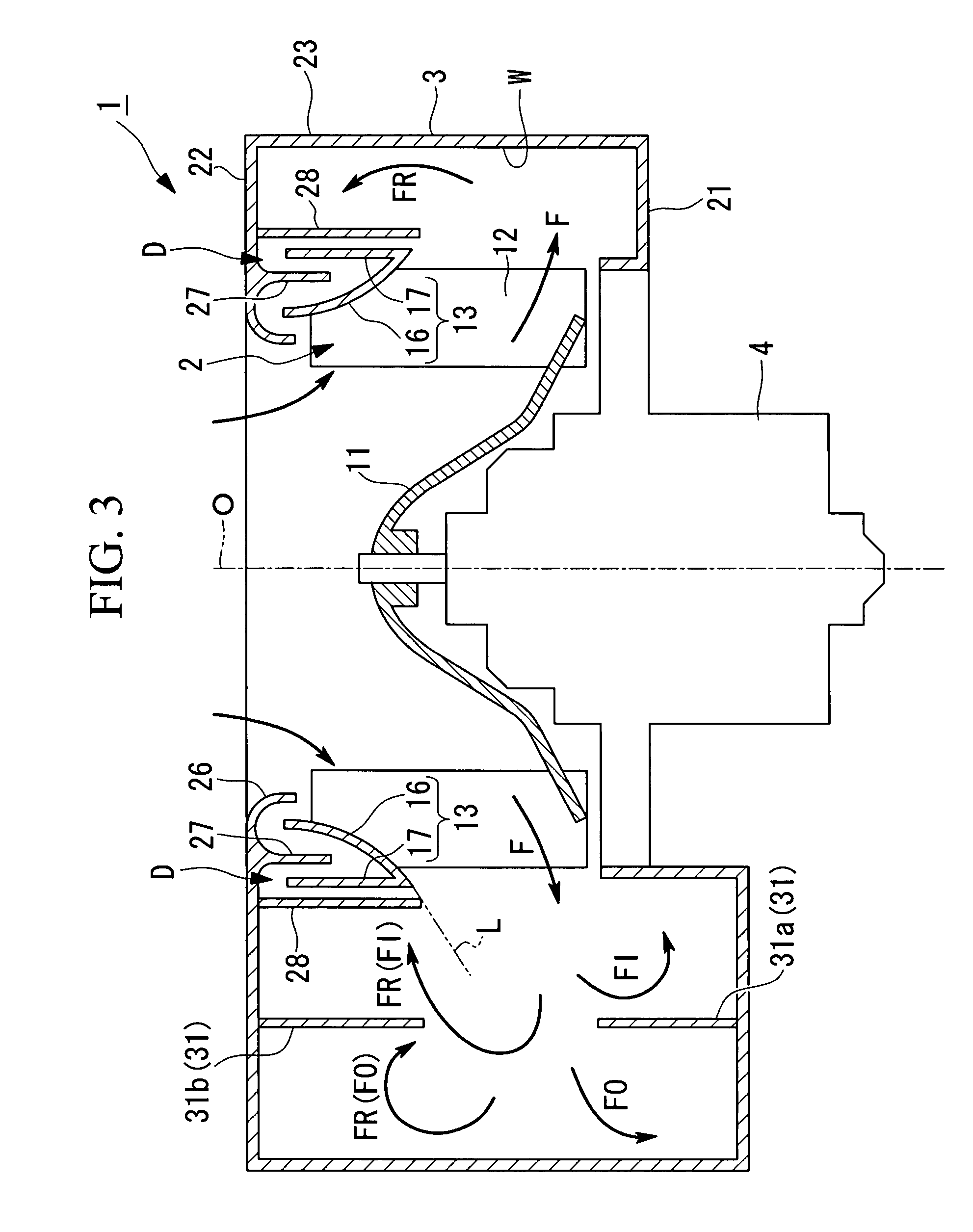
[0058]This centrifugal blower 1 has an impeller 2, a casing 3 that houses the impeller 2 and forms a spiral flow passage W surrounding the radial direction outside of the impeller 2, and a driving device 4 that rotates the impeller 2 about an axis O.

[0059]Here, although not shown in the drawing, provided on a downstream side of the spiral flow passage W of the centrifugal blower 1, are each of the flow passages (face side flow passage, foot side flow passage, defrost side flow passage, and so forth) of, a vehicle air conditioner and a device (heat exchanger for cooling, heater core, and so forth) that conditions the air that has been fed into the spiral flow passage W. At an entry of each of the flow passages there is provided a damper, the opening and closing of...

second embodiment

[0086]A second embodiment of the present invention is described below, with reference to FIG. 6 through FIG. 8.

[0087]A centrifugal blower 51 according to the present embodiment is characterized mainly in that in the centrifugal blower 1 described in the first embodiment, the casing 3 has a wind shielding plate 52 that rises from the area in the vicinity of a start point S of the spiral flow passage W of the bell-mouth 26 toward the outside of the casing 3.

[0088]Hereinafter, structures similar to or the same as those in the centrifugal blower 1 described in the first embodiment are denoted by the same reference symbols, and their detailed description is omitted.

[0089]As shown in FIG. 6, FIG. 7A and FIG. 7B, the wind shielding plate 52 is provided so as to overhang above the casing 3 along the inner periphery of the bell-mouth 26, and is formed in a curved surface having a convex shape toward the radial direction outside.

[0090]Moreover, as shown in FIG. 7A, the wind shielding plate 52...

third embodiment

[0094]A third embodiment of the present invention is described below, with reference to FIG. 9.

[0095]A centrifugal blower 61 of the present embodiment uses a casing 63 in the centrifugal blower 1 shown in the first embodiment instead of the casing 3, and it uses a shroud 73 instead of the shroud 13. Hereinafter, structures similar to or the same as those in the centrifugal blower 1 described in the first embodiment are denoted by the same reference symbols, and their detailed description is omitted.

[0096]The casing 63, is the casing 3 with the backflow suppressing wall 28 removed.

[0097]Moreover, in the casing 63, the casing side barrier 27 is provided so as to oppose a plane that faces the radial direction outside of the shroud 73. In the present embodiment, in the top plate section 22 of the casing 63, an area that opposes a plane that faces the radial direction outside of the shroud 73 is inflected along the plane that faces the radial direction outside of the shroud 73, and this ...


PUM


Abstract

A centrifugal blower has: an impeller; and a casing that houses the impeller. The impeller has: a bottom plate; blades provided on a same circumference of the bottom plate; and a shroud that has the blades interposed between it and the bottom plate, disposed concentric with the bottom plate, and connects end sections of the respective blades. The shroud has: an inclined section that comes closer to the bottom plate moving from a radial direction inside to a radial direction outside; and a shroud side barrier that rises from a position on the radial direction outside of the inclined section towards a side opposite to the bottom plate. The casing has a bell-mouth that opens from a radial direction inside of the shroud to a radial direction outside, and a casing side barrier that projects to an area between the inner periphery of the shroud and the shroud side barrier.

Description

BACKGROUND OF THE INVENTION[0001]1. Field of the Invention[0002]The present invention relates to a centrifugal blower.[0003]2. Description of the Related Art[0004]A centrifugal blower has an impeller, a casing that houses this impeller and forms a spiral flow passage around the radial direction outside of the impeller, and a driving device that rotates the impeller about the axis thereof. In the centrifugal blower the impeller is rotated by the driving device to impart a centrifugal force to the gas that has been taken into the casing and force feeding it into the flow passage. Air is supplied from the impeller to the spiral flow passage sequentially from a start point to a downstream side. Therefore, the internal pressure at the start point of the spiral flow passage is lowest and the internal pressure becomes higher close to the downstream side. The portion of the spiral flow passage one circle from the start point is adjacent to the start point, where the internal pressure is low...

Claims


Application Information

Patent Timeline
Patent Type & Authority Patents(United States)
IPC IPC(8): F04D29/28F04D29/44
CPCF04D29/162F04D29/282F04D29/4226F04D29/444F04D29/665
Inventor EGUCHI, TSUYOSHISUZUKI, ATSUSHITOMINAGA, TETSUO
Owner MITSUBISHI HEAVY IND LTD
Why Eureka
Try Eureka