
Self-contained hydraulic thruster for vessel

a self-contained, hydraulic technology, applied in the direction of motor-driven power plants, special-purpose vessels, vessel construction, etc., can solve the problems of lack of effective extension and retraction mechanisms of lower units, insufficient power supply of thrusters' single lower units, and available marine thrusters, etc., to achieve greater tilt, reduce corrosion, and improve the effect of stowing efficiency of lower units

Active Publication Date: 2011-02-08
WILLIAMS JOHN T
View PDF20 Cites 8 Cited by
  • Summary
  • Abstract
  • Description
  • Claims
  • Application Information

AI Technical Summary

Benefits of technology

[0012]It is another object of this invention to provide a self-contained hydraulic thruster for vessel which is easily extended and retracted. Design features allowing this object to be achieved include a lower unit actuator attached at one end to a tube, and at the other to a shaft. Benefits associated with reaching this objective include decreased operator work load, and increased convenience of operation.
[0020]It is yet another object of this invention to provide a self-contained hydraulic thruster for vessel which is economical to build. Design features allowing this object to be achieved include the use of components made of readily available materials, and commercially available components such as an existing steering motor, overhung load adapter, hydraulic actuator, hydraulic power pack, hydraulic fluid reservoir, lower unit, propeller, steering gear, drive gear, and hydraulic lines. Benefits associated with reaching this objective include reduced cost, and hence increased availability.

Problems solved by technology

There are a number of problems associated with currently available marine thrusters.
Another problem with current designs is the lack of an effective extension and retraction mechanism for lower units.
Another problem is providing for power assist, so as to avoid the greater work of manually extending and retracting the lower unit.
Still another extension / retraction problem lies in adequately supporting the lower end of an extended lower unit, given the long resultant length of the lower unit when extended, and the resultant longer moment arm between the lower unit's mounting point at its upper end, and the propeller's location at its lower end.
Another problem with existing designs: the hydraulic fluid reservoir is disposed on the base of the marine thruster, where it is incapable of supplying enough fluid head to self-prime the power pack, and to facilitate hydraulic fluid flow to the hydraulic power pack.
Still another problem is where a marine thruster's single lower unit propeller does not supply enough power to adequately propel a vessel upon which it is mounted.
Other problems with existing designs include insufficient reinforcement at the lower unit tilt actuator attach point on the base, inadequate bearing surface at the lower unit pivot point, and excess steering motor stress.
In addition, the mounting of the hydraulic fluid reservoir on the base of this design provides inadequate flow from the hydraulic fluid tank for self-priming and gravitational flow from hydraulic fluid tank to power pack.

Method used


Image

  • Self-contained hydraulic thruster for vessel
  • Self-contained hydraulic thruster for vessel
  • Self-contained hydraulic thruster for vessel

Examples


Embodiment Construction

[0047]This disclosure is based upon, and builds on, parent disclosure U.S. utility application Ser. No. 11 / 999,531 filed Dec. 6, 2007 entitled Self-Contained Hydraulic Thruster for Vessel, which is hereby incorporated by reference into this disclosure. Drawing sheets 1-10 containing FIGS. 1-14, and the passages in this Specification pertaining to these, are substantially the same as in the parent disclosure. Drawing sheets 11-20 containing FIGS. 15-26, and the passages in this Specification pertaining to these, describe the improvements and refinements which are introduced in this disclosure. Accordingly, drawing sheets 1-10 containing FIGS. 1-14 will first be described below, followed by a description of drawing sheets 11-20 containing FIGS. 15-26.

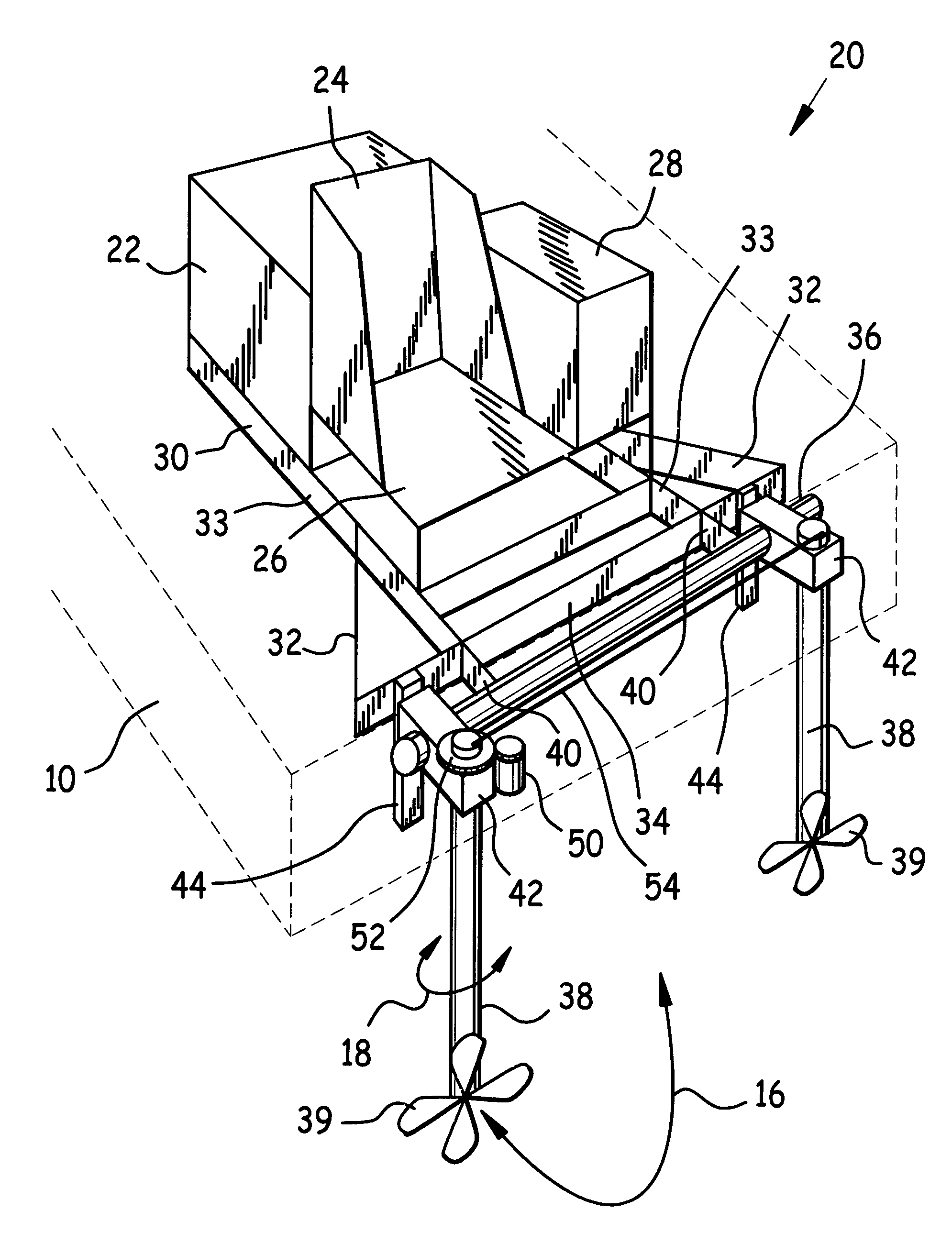
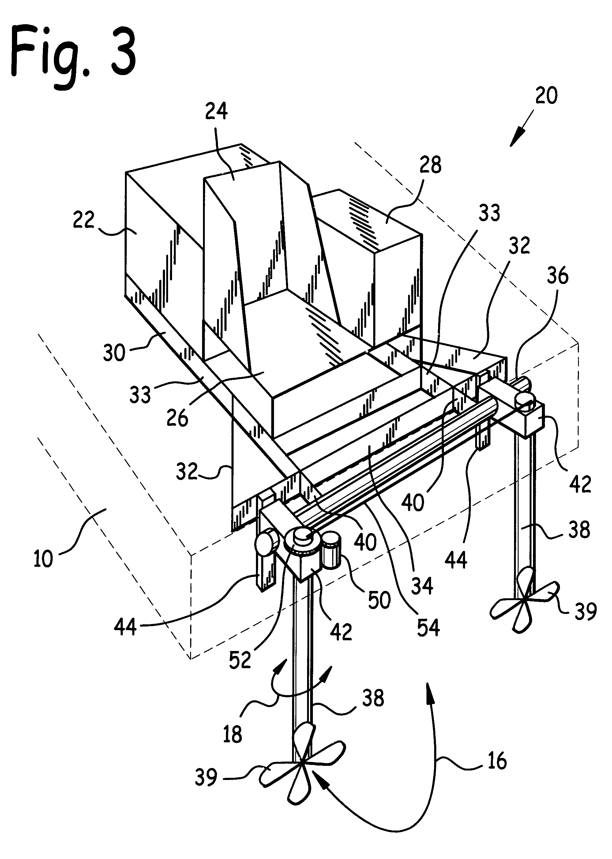
[0048]FIG. 3 is a rear quarter isometric view of self-contained hydraulic thruster 20. Hydraulic thruster 20 comprises base 30 which supports hydraulic power pack 22 and helm platform 26. Helm platform 26 in turn supports helm 24 and hydr...


PUM


Abstract

A self-contained hydraulic thruster for vessel. The hydraulic thruster incorporates a lower unit housing tiltably attached to a lower unit mounting tube attached to a base, a tube whose upper end is attached through the lower unit housing, and a shaft slidably disposed within the tube. A substantial length of tube extends downwards from the lower unit housing, thus providing support for the shaft. An actuator is disclosed which extends and retracts the shaft relative to the tube. A steering clamp is releasably attached to an end of the shaft which protrudes through the top of the lower unit housing. A steering clamp key traveling in a shaft keyway, or a shaft key in combination with a steering clamp keyway, help maintain constant the angular orientation between the steering clamp and the shaft. A steering gear meshing with a steering assembly, or an actuator driving a tie rod, provide steering.

Description

CLAIM FOR PRIORITY[0001]This utility patent application is a Continuation-In-Part of U.S. utility application Ser. No. 11 / 999,531 filed Dec. 6, 2007 now U.S. Pat. No. 7,654,875 entitled Self-Contained Hydraulic Thruster for Vessel, which was based upon U.S. provisional patent application Ser. No. 60 / 903,400 filed Feb. 26, 2007 entitled Self-Contained Hydraulic Thruster for Vessel; and claims the benefit of the earlier filing date of these applications.BACKGROUND OF THE INVENTIONField of the Invention[0002]This invention relates to vessel propulsion systems, and in particular to a self-contained hydraulic thruster for vessel.BACKGROUND OF THE INVENTION[0003]Marine thrusters typically mount on barges and flat boats, and are used as propulsion for these vessels. One type of marine thruster employs a prime mover such as a diesel engine driving a hydraulic pump, together known as a “power pack”, and the resultant pressurized hydraulic fluid may be employed to drive a propeller attached t...

Claims


Application Information

Patent Timeline
IPC IPC(8): B63H21/12
CPCB63H5/125B63H23/26B63H25/42
Inventor WILLIAMS, JOHN T.
Owner WILLIAMS JOHN T
Learn More