Supercharge Your Innovation With Domain-Expert AI Agents!

Parallel calculation method and device

a computing method and a technology of parallel computing, applied in the field of parallel computing methods and systems suitable for molecular simulation, can solve the problems of inability to realize measurement, and inability to handle a matrix greater than the memory capacity of the host machine, so as to reduce the amount of computation, increase work areas, and reduce the amount of transfer

Inactive Publication Date: 2011-02-08
NEC SOLUTION INNOVATORS LTD
View PDF14 Cites 0 Cited by
  • Summary
  • Abstract
  • Description
  • Claims
  • Application Information

AI Technical Summary

Benefits of technology

The present invention relates to a parallel computing method and system for molecular orbital calculations, specifically the RHF method, which is a time-consuming task that requires a large amount of computer memory and processing power. The invention aims to enhance the speed of calculating the Fock matrix, which is the most time-consuming part of the SCF method, by using a single host machine and parallel computers or a cluster of computers to execute the calculation. However, existing methods have limitations in terms of the size of the matrix that can be handled by the host machine, and using multiple host machines in parallel is not always cost-effective. The invention proposes a new method and system that overcomes these limitations and allows for faster and more efficient molecular orbital calculations.

Problems solved by technology

However, when a large-scale calculation, e.g., N is some ten thousands, has to be done, an enormous amount of disk capacity is needed.
However, in these methods, matrix calculation such as diagonalization is done by the so-called host machine, these methods entail the problem that it is impossible to handle a matrix greater than the memory capacity of the host machine.
However, this measure is not so easy to realize because it is costly.
Further, increasing the number of the coupled computers also leads to speedup.
However, a cluster of general purpose computers entails the problem in that it is impossible for each single computer to execute matrix calculation of a large-scale molecule because of the memory capacity for single computer being low, and that it is impossible to hold the whole matrix on the memory of a single computer if the number of molecular orbitals amounts to some ten thousands.

Method used


Image

  • Parallel calculation method and device
  • Parallel calculation method and device
  • Parallel calculation method and device

Examples


example 1

Cyclical Density Matrix Scheme

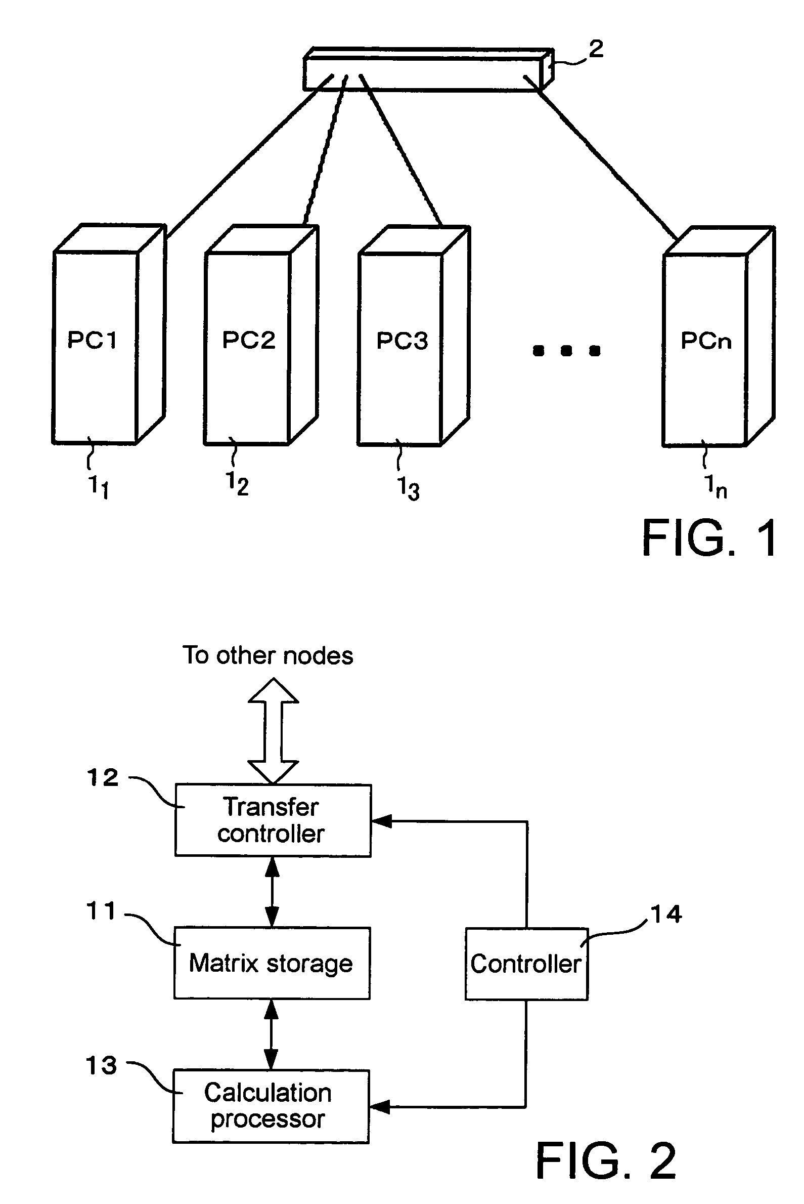
[0044]First, one embodiment called a cyclical density matrix scheme will be described. Again, Fock matrix F is defined as Eq. (7).

[0045]Frs=Hrs+∑t,u=1N⁢Dtu⁡[(rs❘tu)-12⁢(rt❘su)](7)

[0046]In Eq. (7), Frs, Hrs, Dtu (r, s, t, u=1, . . . , N) are matrixes. Since the number in which a matrix is divided is 4, r, s, t and u are each divided into two regions, as shown in Eq. (8).

R1, S1, T1, U1=1, . . . , N / 2, R2, S2, T2, U2=N / 2+1, . . . , N,   (8)

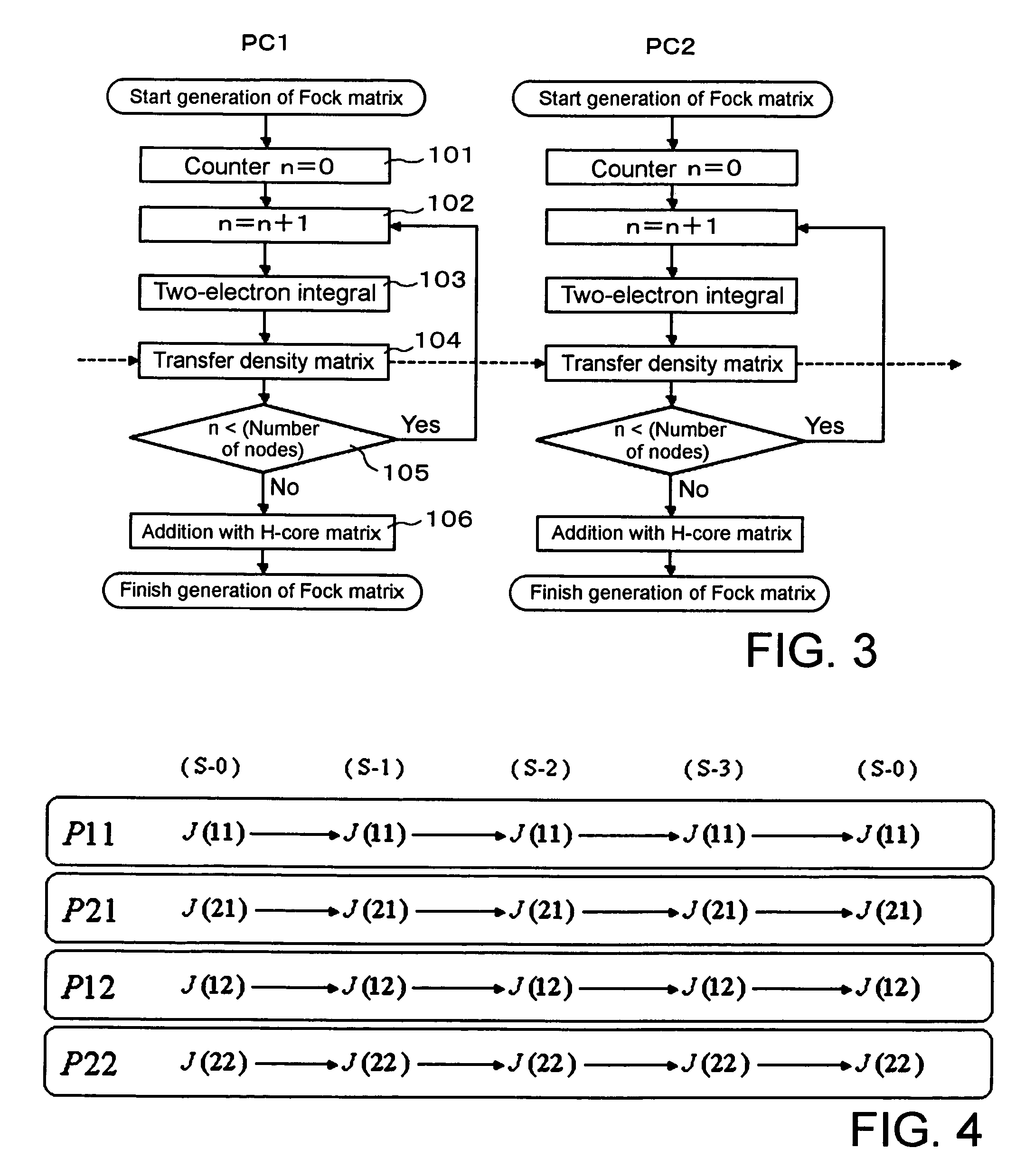
[0047]With this regional division, a matrix is divided into four. The divided submatrixes are named as in Eq. (9).

[0048]F⁡(11)=FR⁢⁢1⁢S⁢⁢1H⁡(11)=HR⁢⁢1⁢S⁢⁢1D⁡(aa)=DT⁢⁢1⁢U⁢⁢1F⁡(21)=FR⁢⁢2⁢S⁢⁢1H⁡(21)=HR⁢⁢2⁢S⁢⁢1D⁡(ba)=DT⁢⁢2⁢U⁢⁢1F⁡(12)=FR⁢⁢1⁢S⁢⁢2H⁡(12)=HR⁢⁢1⁢S⁢⁢2D⁡(ab)=DT⁢⁢1⁢U⁢⁢2F⁡(22)=FR⁢⁢2⁢S⁢⁢2H⁡(22)=HR⁢⁢2⁢S⁢⁢2D⁡(bb)=DT⁢⁢2⁢U⁢⁢2.](9)

When these are represented in an integrated manner, they can be represented as in Eq. (10).

[0049]F⁡(RS)={F⁡(11),F⁡(21),F⁡(12),F⁡(22)}F⁡(RS)={H⁡(11),H⁡(21),H⁡(12),H⁡(22)}D⁡(TU)={D⁡(aa),D⁡(ba),D⁡(ab)...

example 2

Double Cyclical Density Matrix Scheme

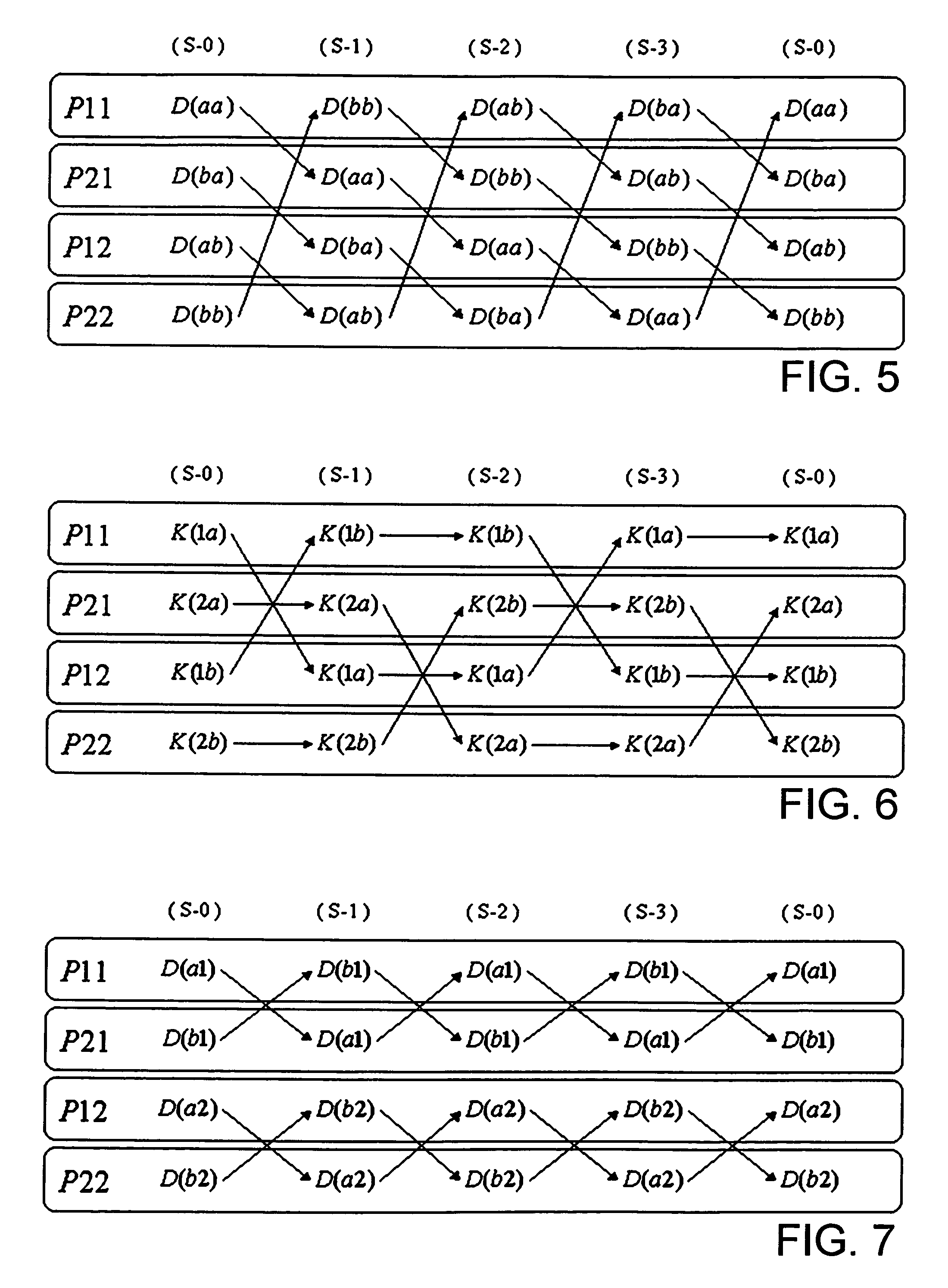
[0061]Next, a mode called a double cyclical density matrix scheme will be described. In this mode, a duplication of density matrix D is used to halve the number of calculations for integration, thereby reduce computational time. The symbols used here are the same as those used in the aforementioned cyclical density matrix scheme. In this scheme, Eq. (7) is decomposed as in Eq. (16).

[0062]Frs=Hrs+Jrs-12⁢KrsJrs=∑t=1N⁢∑u=1N⁢Dtu⁡(rs❘tu)Kru=∑t=1N⁢∑s=1N⁢Dts⁡(rs❘tu)](16)

where, J and K are matrixes presenting summations of Coulomb integrals and exchange integrals, respectively. This can be written down for every region and every node in a similar manner as for the case of the cyclical density matrix scheme, and Eqs. (17) and (18) are obtained.

[0063]P⁢⁢11⁢:⁢F⁡(11)=H⁡(11)+J⁡(11)-K⁡(11) / 2P⁢⁢21⁢:⁢F⁡(21)=H⁡(21)+J⁡(21)-K⁡(21) / 2P⁢⁢12⁢:⁢F⁡(12)=H⁡(12)+J⁡(12)-K⁡(12) / 2P⁢⁢22⁢:⁢F⁡(22)=H⁡(22)+J⁡(22)-K⁡(22) / 2](17)P⁢⁢11⁢:⁢J⁡(11)=D⁢(aa)⁢(11❘aa),J⁡(11)=D⁢(bb)⁢(11❘bb),J⁡(1...

example 3

Quadruple Cyclical Density Matrix Scheme, Part-1

[0080]Next, a mode called a quadruple cyclical density matrix scheme will be described. In this mode, density matrix D and its duplications, four in total, are prepared, and the symmetry between (rs|tu)(tu|rs) in two-electron integration is made use of to further reduce calculation of integrals compared to the double cyclical density matrix scheme, hence reduce calculation time. The symbols used here are the same as those used in the aforementioned cyclical density matrix scheme. In this scheme, Eq. (7) is decomposed as in Eqs. (22) to (24).

[0081]⁢Frs=Hrs+Jrs-12⁢Krs⁢Jrs=J⁢⁢1rs+J⁢⁢2rs⁢Kru=K⁢⁢1ru+K⁢⁢2ru⁢J⁢⁢1rs=∑t=1,m<=nN⁢∑u=1,m<=nN⁢Dtu⁡(rs⁢❘⁢tu)⁢d⁡(m,n)⁢J⁢⁢2tu=∑r=1,m<=nN⁢∑s=1,m<=nN⁢Drs⁡(rs⁢❘⁢tu)⁢d⁡(m,n)⁢K⁢⁢1ru=∑t=1,m<=nN⁢∑s=1,m<=nN⁢Dts⁡(rs⁢❘⁢tu)⁢d⁡(m,n)⁢K⁢⁢2ts=∑r=1,m<=nN⁢∑u=1,m<=nN⁢Dru⁡(rs⁢❘⁢tu)⁢d⁡(m,n)](22)

m=(s−1)N+r, n=(u−1)N+t,   (23)

d(m,n)=1 for m≠n, ½ for m=n   (24)

[0082]This represents that Coulomb integral ...


PUM

PropertyMeasurementUnit
densityaaaaaaaaaa
structuresaaaaaaaaaa
physical propertiesaaaaaaaaaa

Abstract

A method for executing calculation of the Hartree-Fock method in a molecular orbital method by a distributed memory parallel computing system includes the steps of: using a computer cluster made up of a plurality of computers; dividing a density matrix into multiple density submatrixes and distributing them to the individual computers and storing therein; and executing calculation processes such as two-electron integration or the like relating to density submatrixes in each computer while sequentially transferring the multiple density submatrixes between the multiple computers.

Description

TECHNICAL FIELD[0001]The present invention relates to a parallel computing method and system suitable for molecular simulation or the like, and in particular relates to a parallel computing method and system suitable for molecular orbital calculation by the RHF (Restricted Hartree-Fock) method.BACKGROUND ART[0002]With development of quantum chemistry theory and with advancement of computer technologies, it has become possible to perform precise simulations of structures and physical properties of molecules, and chemical bonds, molecular orbitals and electron states in molecules. This technique is generally called a molecular orbital method. Of the molecular orbital methods, an ab initio (non-empirical) molecular orbital method that in principal does not depend on empirical parameters needs an enormous computational amounts in order to solve Schrödinger equations even if it is performed by approximate calculations. Accordingly, it has been only possible to apply it to small molecules...

Claims


Application Information

Patent Timeline
Patent Type & Authority Patents(United States)
IPC IPC(8): G06G7/48G06G7/58G01N33/48G01N31/00G06F17/13G06F17/16G06F19/00
CPCG06F17/13
Inventor TAKADA, TOSHIKAZUYAMAMOTO, JUN-ICHINAKATA, KAZUTO
Owner NEC SOLUTION INNOVATORS LTD
Features
  • R&D
  • Intellectual Property
  • Life Sciences
  • Materials
  • Tech Scout
  • Unparalleled Data Quality
  • Higher Quality Content
  • 60% Fewer Hallucinations
Learn More