System and method for ignition of a gaseous or dispersed fuel-oxidant mixture

a technology of gaseous or dispersed fueloxidant and ignition system, which is applied in the direction of electric fuzes, intermittent jet plants, instruments, etc., can solve the problems of reducing combustion efficiency, reducing combustion efficiency, and reducing combustion efficiency

Active Publication Date: 2011-02-15
SOUNDBLAST TECH
View PDF37 Cites 32 Cited by
  • Summary
  • Abstract
  • Description
  • Claims
  • Application Information

AI Technical Summary

Problems solved by technology

Existing systems and methods for ignition of a gaseous or dispersive fuel-oxidant mixture are inefficient, costly, and often dangerous.
Modern spark plug-based ignition technology used in internal combustion engines leaves unspent fuel in the cylinders of such engines after the combustion cycle and requires use of a catalytic converter to convert toxic combustion byproducts to safer byproducts but which still result in dangerous pollutants being emitted into the atmosphere.
Moreover, spark plugs degrade in performance over time resulting in lower and lower combustion efficiency and therefore lower and lower fuel mileage and greater and greater pollution.
However, the fuel-oxidant mixture ignition methods that have been used in such pulse detonation engines require the use of dangerous and costly fuel-oxidant mixtures and a significant amount of energy to achieve detonation.
Moreover, the timing and the magnitudes of the detonations produced in such engines are difficult to control due to the limitations of the ignition methods being deployed.

Method used


Image

  • System and method for ignition of a gaseous or dispersed fuel-oxidant mixture
  • System and method for ignition of a gaseous or dispersed fuel-oxidant mixture
  • System and method for ignition of a gaseous or dispersed fuel-oxidant mixture

Examples


first embodiment

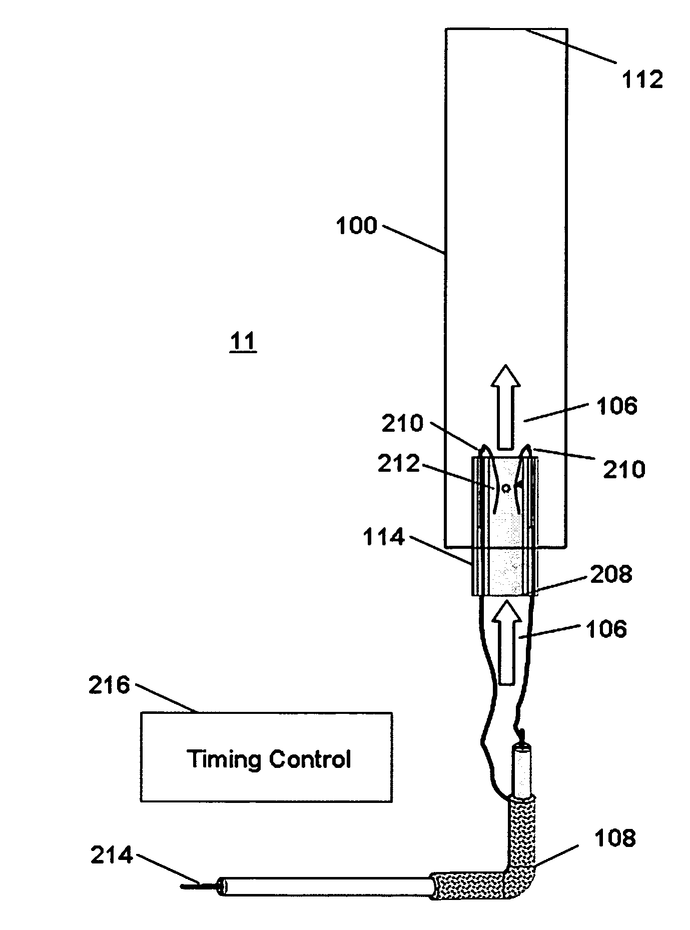
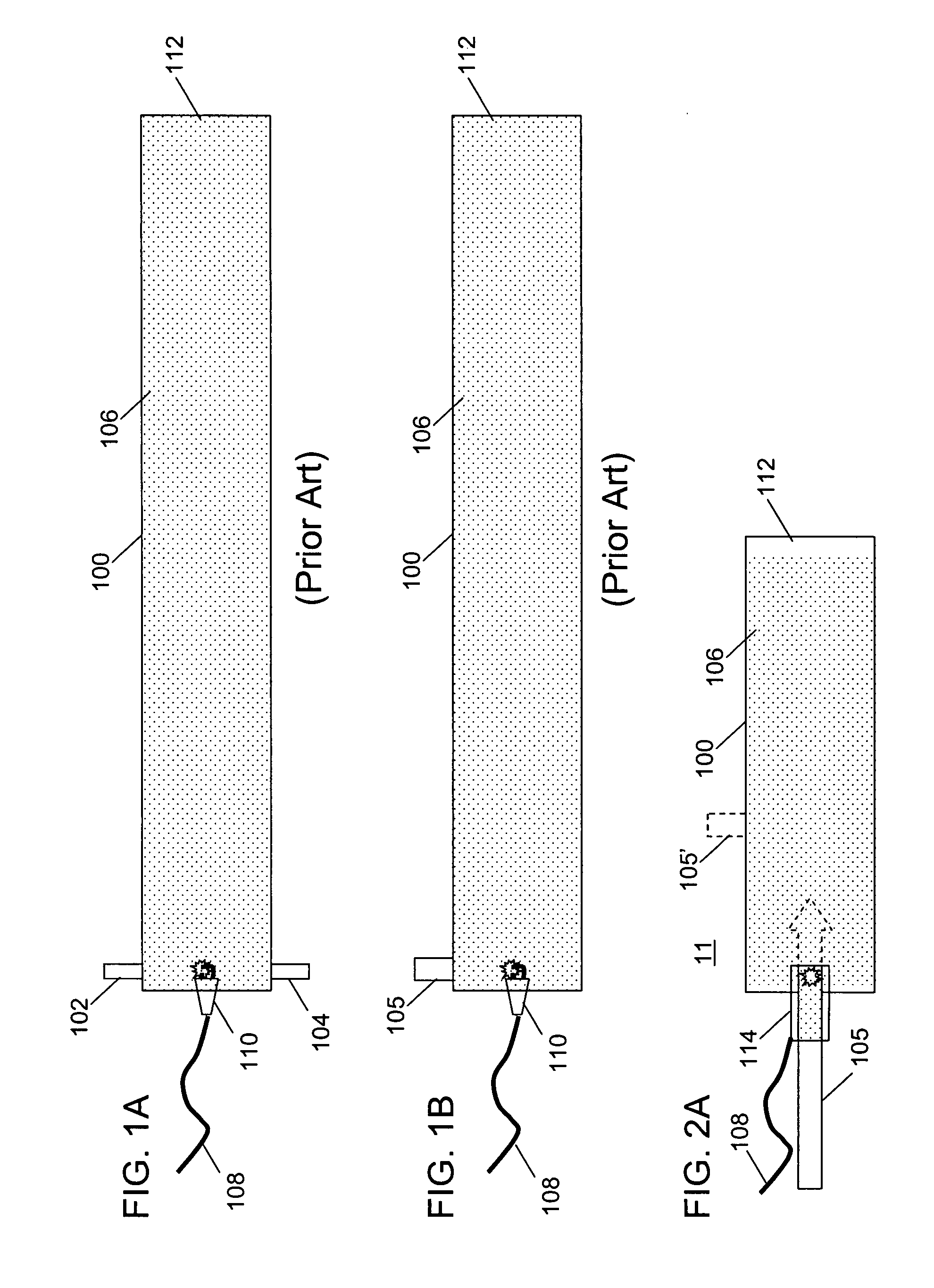
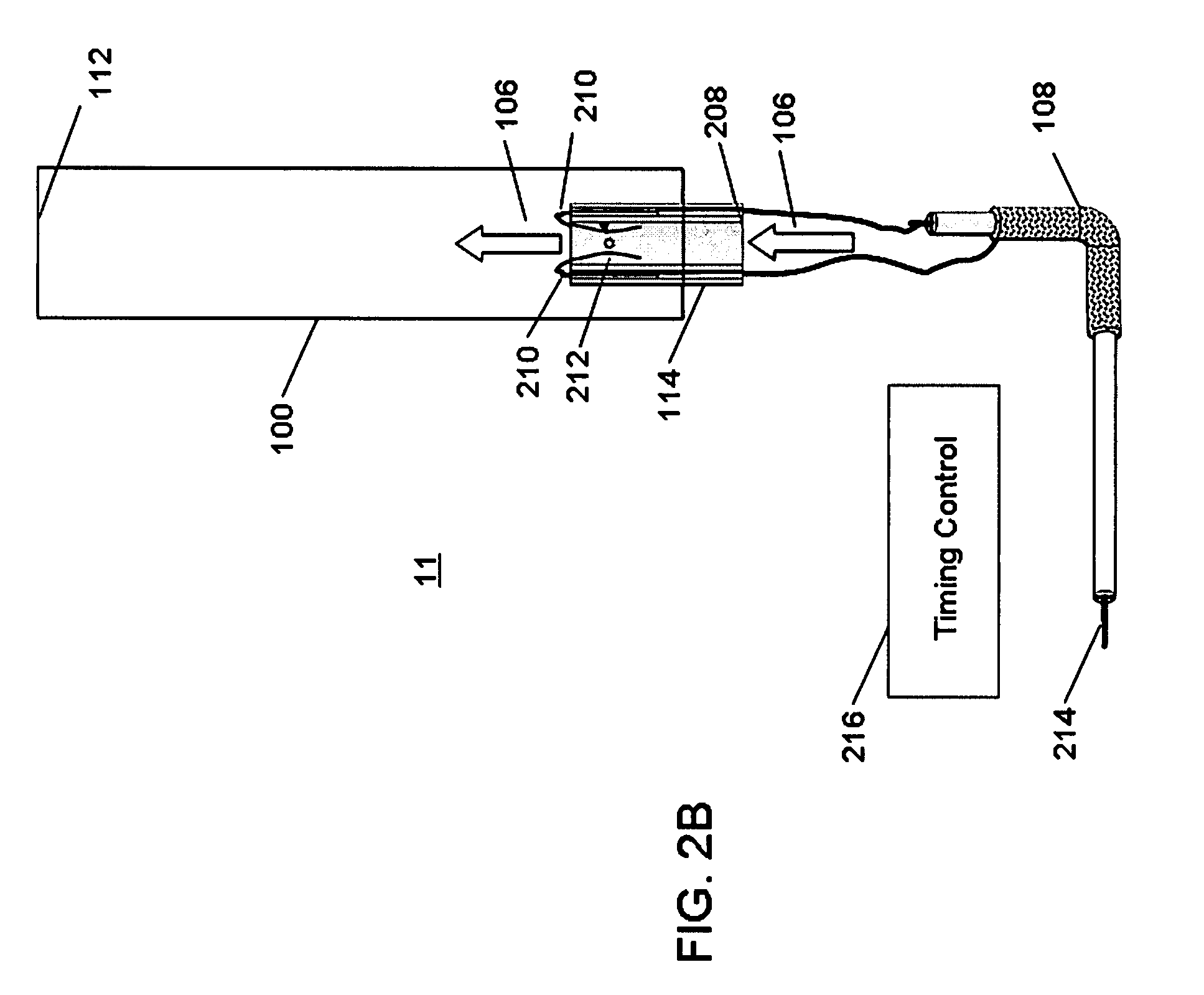
[0051]FIG. 2B depicts the detonator of the present invention that functions by creating an electrical arc within a stream of a detonatable gas mixture. As shown in FIG. 2B, a gas mixture 106 of a combustible gas and oxidizer in the correct detonable ratio is passed into a detonation tube 100 via fill point 208 of detonator 114. When the tube is substantially full, high voltage wire 108 is triggered at high voltage pulse input 214 to cause a spark 212 to occur across bare wires 210 and to pass through the gas mixture 106 flowing into the detonation tube 100 to initiate detonation of the gas in the detonation tube 100. Triggering of high voltage pulse is controlled by timing control mechanism 216.

second embodiment

[0052]FIG. 2C depicts the detonator of the present invention that also functions by creating an electrical arc within a stream of a detonatable gas mixture. As shown in FIG. 2C, a gas mixture 106 of a combustible gas and oxidizer in the correct detonable ratio is passed into a detonation tube 100 via fill point 208 of detonator 114. When the tube is substantially full, high voltage wire 108 is triggered at high voltage pulse input 214 to cause a spark 212 to occur across bare wires 210 and to pass through the gas mixture 106 flowing into the detonation tube 100 to initiate detonation of the gas in the detonation tube 100. In this variation the spark is initiated within detonator 114 and then it is quickly swept along the two diverging conductors into the detonation tube 100 by the flowing gas, the length of the spark increasing as it travels into the detonation tube 100. When a spark is initiated in a small gap it creates a stable low impedance zone that is capable of conducting the...


PUM


Abstract

An improved system and method for ignition of a gaseous or dispersive fuel-oxidant mixture is provided where a gaseous or dispersive fuel-oxidant mixture is supplied to a detonator tube having a fill point and an open end and an igniter placed at an ignition point within the detonator tube is ignited while the gaseous or dispersive fuel-oxidant mixture is flowing through the detonator tube. A detonation impulse is produced at the ignition point that propagates to the open end of said detonator tube where it can be supplied to a detonation tube having an open end, to an internal combustion engine, a combustion chamber, and to a pulse detonation engine.

Description

CROSS REFERENCE TO RELATED APPLICATIONS[0001]This application claims priority to U.S. Provisional Patent Application 60 / 792,420, filed Apr. 17, 2006, and to U.S. Provisional Patent Application 60 / 850,685, filed Oct. 10, 2006, which are both incorporated herein by reference. This application is also related to a U.S. Provisional Patent Application filed concurrently on Oct. 10, 2006, titled “A System and Method for Generating and Directing Very Loud Sounds”.FIELD OF THE INVENTION[0002]The present invention relates generally to a system and method for ignition of a gaseous or dispersive fuel-oxidant mixture. More particularly, the present invention relates to controlling the detonation of a gaseous or dispersive fuel-oxidant mixture flowing within a tubular structure.BACKGROUND OF THE INVENTION[0003]Existing systems and methods for ignition of a gaseous or dispersive fuel-oxidant mixture are inefficient, costly, and often dangerous. Modern spark plug-based ignition technology used in ...

Claims


Application Information

Patent Timeline
Patent Type & Authority Patents(United States)
IPC IPC(8): G01V1/06
CPCF02K7/02F42D3/06F42B3/02F42B3/00Y02T50/60
Inventor FULLERTON, LARRY W.
Owner SOUNDBLAST TECH
Why Eureka
Try Eureka