Grid member and vehicle front structure with the grid member

a technology for vehicle front structure and grid member, which is applied in the directions of roofs, vehicular safety arrangments, transportation and packaging, etc., can solve problems such as and achieve the effect of reducing damage to parts within the engine compartment of the vehicl

Inactive Publication Date: 2011-02-15
NISSAN MOTOR CO LTD
View PDF22 Cites 39 Cited by
  • Summary
  • Abstract
  • Description
  • Claims
  • Application Information

AI Technical Summary

Benefits of technology

[0007]In one or more embodiments of the present invention, a grid member includes a substantially horizontally extending bridge and can reduce damage to a part within a vehicle engine compartment even when a rear end portion of the bridge in the substantially horizontal state is brought into contact with the part due to an external force applied to the bridge from a forward direction of the vehicle, and provide a vehicle front structure with the grid member.

Problems solved by technology

This tends to result in damage to the part within the engine compartment.

Method used


Image

  • Grid member and vehicle front structure with the grid member
  • Grid member and vehicle front structure with the grid member
  • Grid member and vehicle front structure with the grid member

Examples


first embodiment

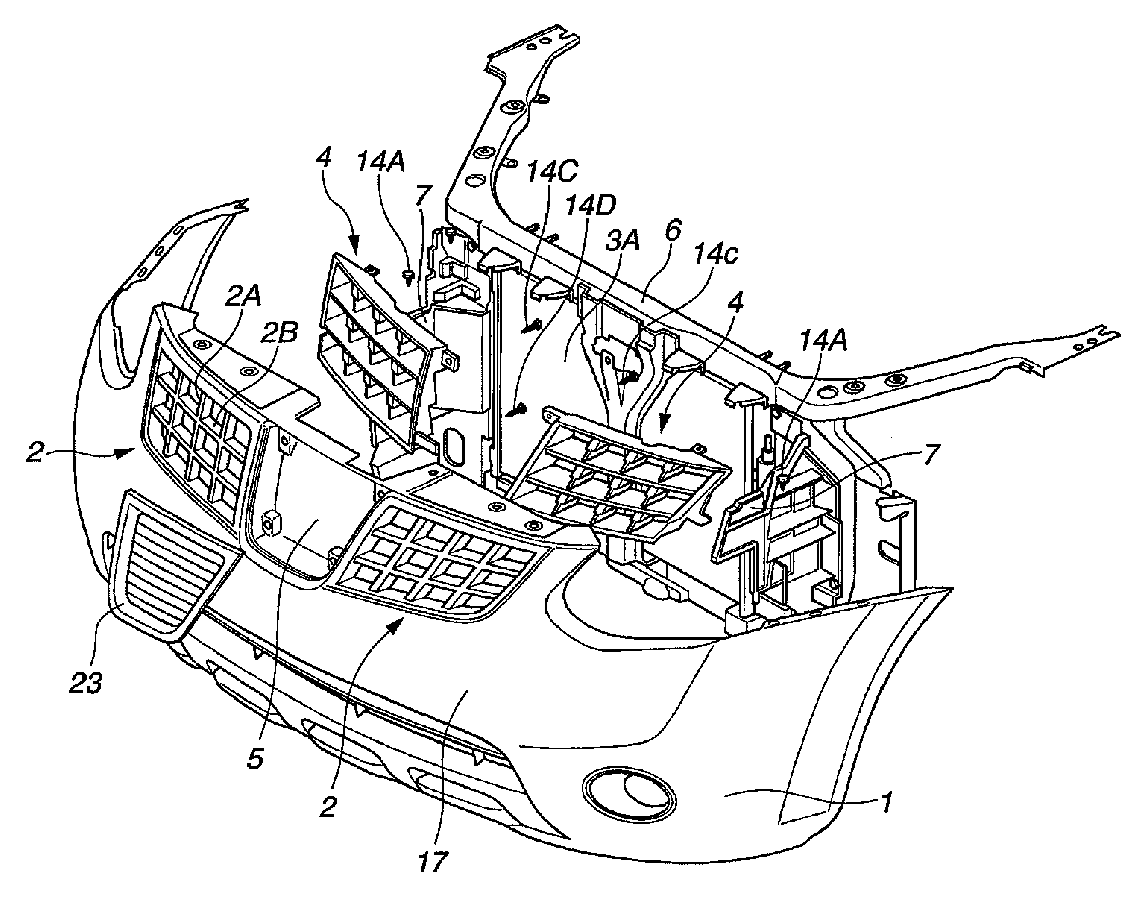
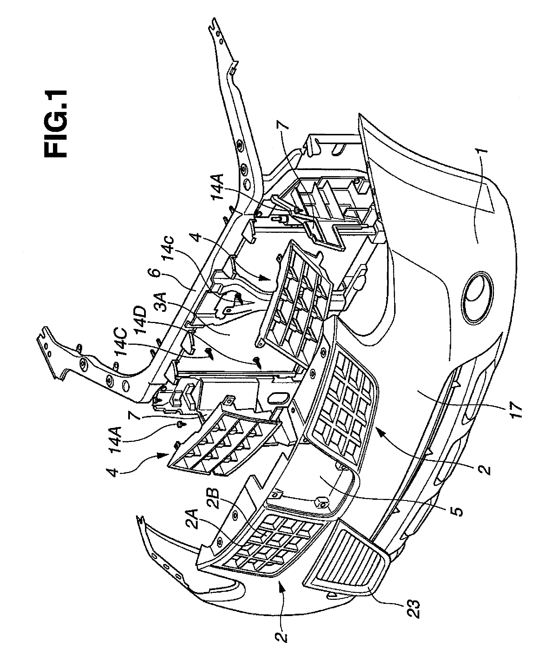
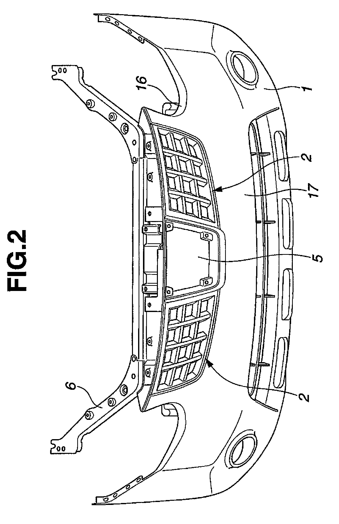
[0035]FIG. 1 to FIG. 16 are diagrams showing a vehicle front structure of the invention.

[0036]As shown in FIG. 1 to FIG. 4, the vehicle front structure includes grille 2 formed on fascia 1, heat exchanger 3 disposed on a rear side of grille 2, and grille reinforcement members 4 disposed near grille 2 on a front side of heat exchanger 3. Fascia 1 serves as a support member for grille reinforcement members 4. Grille 2 serves as an outside air introducing portion. Heat exchanger 3 is a part disposed within an engine compartment and includes condenser 3A and radiator 3B. Each of grille reinforcement members 4 is a grid member.

[0037]The fascia 1 is constructed to cover vehicle body parts which include a bumper reinforcement, not shown, that is disposed on a front side of the engine compartment. Fascia 1 includes a bumper 17 that extends in a width direction of the vehicle so as to cover the bumper reinforcement and serves as a projection that projects in a forward direction of the vehicl...

fourth embodiment

[0073]FIG. 21 and FIGS. 22A-22D show a vehicle front structure of the invention. The fourth embodiment differs from the first embodiment in the arrangement of the support portions 13A and 13B of the grille reinforcement member 4 and a projecting portion 22. Specifically, the support portions 13A and 13B are provided on only the lower side of the grille reinforcement member 4. Further, instead of the projecting portion 17 formed in the fascia 1, the projecting portion 22 projecting in the forward direction of the vehicle is provided on the upper side of the grille reinforcement member 4 which lacks the support portion 13A. Further, the fourth embodiment differs from the first and third embodiments in the arrangement of the fragile portions 10B and 11B and the high strength portions 10A and 11A. Specifically, as shown in FIG. 21, the fragile portion 10B and the high strength portion 10A are respectively disposed on the front side and the rear side of the vertical bridge upper portion ...

fifth embodiment

[0075]FIG. 23 to FIG. 24D show a vehicle front structure of the invention. The fifth embodiment differs from the first, third and fourth embodiments in using grille reinforcement member 4 with inclined lateral bridge 9. In the fifth embodiment, when external force F is applied to the vehicle front structure, the vertical bridge 8 is deformed to turn the lateral bridge 9 without turning the whole grille reinforcement member 4.

[0076]As shown in FIG. 23, the lateral bridge 9 is inclined to downwardly direct the front end 9B thereof in the fore-and-aft direction of the vehicle. Further, the lateral bridges 9 are arranged such that the front ends 9B and the rear ends 9A are respectively aligned in the height direction of the vehicle. Further, the fragile portion 10B and the high strength portion 10A are respectively disposed on the rear side and the front side of the vertical bridge upper portion 10 in the fore-and-aft direction of the vehicle, and the high strength portion 11A and the f...


PUM


Abstract

A front structure for a vehicle has a grid member configured to allow outside air to be introduced from a forward direction of the vehicle into a compartment of the vehicle, and a part within the compartment disposed on a rear side of the grid member. The grid member has a first bridge and a second bridge intersecting with the first bridge. One of the first bridge and the second bridge has a bridge upper portion having a fragile portion on one of a front side thereof and a rear side thereof in a fore-and-aft direction of the vehicle, and a bridge lower portion having a fragile portion on one of a front side thereof and a rear side thereof in the fore-and-aft direction. The fragile portion of the bridge upper portion and the fragile portion of the bridge bottom portion are on opposite sides in the fore-and-aft direction.

Description

PRIORITY APPLICATION[0001]This application claims priority to Japanese Patent Application No. 2006-355212, filed on Dec. 28, 2006 and Japanese Patent Application No. 2007-272397, filed on Oct. 19, 2007. The entire disclosure of Japanese Patent Application No. 2006-355212 and Japanese Patent Application No. 2007-272397 are hereby incorporated herein by reference.BACKGROUND OF INVENTION[0002]1. Field of the Invention[0003]The present invention relates to a grid member that is disposed at a front portion of a vehicle in order to introduce outside air into an engine compartment and having two bridges intersecting each other, and further relates to a vehicle front structure with the grid member.[0004]2. Description of the Related Art[0005]A conventional front structure of a vehicle is disclosed in Japanese Patent Provisional Publication No. 2005-212631. The conventional front structure includes an outside air introducing port for introducing an outside air into an inside of an engine com...

Claims


Application Information

Patent Timeline
Patent Type & Authority Patents(United States)
IPC IPC(8): B60R19/52
CPCB60R19/52B60R2019/525
Inventor TAZAKI, YUICHIENDOU, MAYUMI
Owner NISSAN MOTOR CO LTD
Why Eureka
Try Eureka