Method and apparatus for obtaining the distance from an optical measurement instrument to an object under test

a technology of optical measurement and distance, applied in the field of optical measurement instruments, can solve problems such as measurement inaccuracy, measurement error, and misinterpretation of the radius of curvature of either a surface or wave of light, and achieve the effect of avoiding measurement errors and avoiding measurement errors

Active Publication Date: 2011-02-15
AMO DEVMENT
View PDF4 Cites 21 Cited by
  • Summary
  • Abstract
  • Description
  • Claims
  • Application Information

AI Technical Summary

Benefits of technology

[0006]Accordingly, it would be advantageous to provide an arrangement that can be used to determine accurately the distance between a reference plane of an optical measurement instrument and a reference plane of an object under test. It would further be advantageous to provide such an arrangement that can be in a standalone configuration, or integrated into the optical measurement instrument.
[0007]It would also be advantageous to provide a method for accurately measuring or computing the distance from a surface of an eye or other object under test to an optical or mechanical reference plane of a measurement instrument. Other and further objects and advantages will appear hereinafter.

Problems solved by technology

A misalignment of this distance (hereinafter referred to as the “Z-Distance”) can result in measurement inaccuracies.
In the case of corneal topography, keratometry and wavefront aberration measurements the result can be a misinterpretation of the radius of curvature of either a surface or waves of light, or error in measurement of other parameters such as ocular refraction, higher order aberrations or pupil size.

Method used


Image

  • Method and apparatus for obtaining the distance from an optical measurement instrument to an object under test
  • Method and apparatus for obtaining the distance from an optical measurement instrument to an object under test
  • Method and apparatus for obtaining the distance from an optical measurement instrument to an object under test

Examples


Embodiment Construction

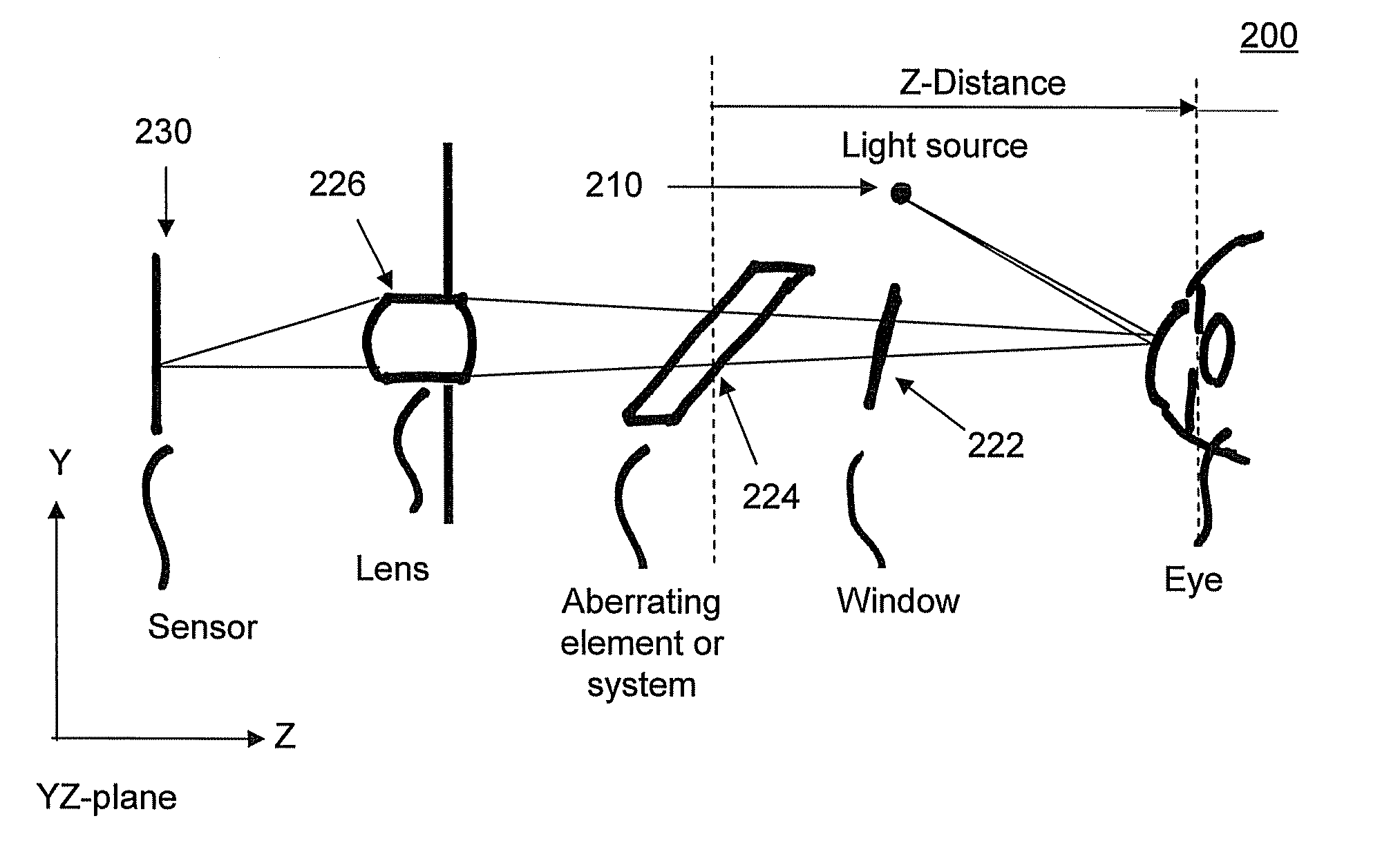
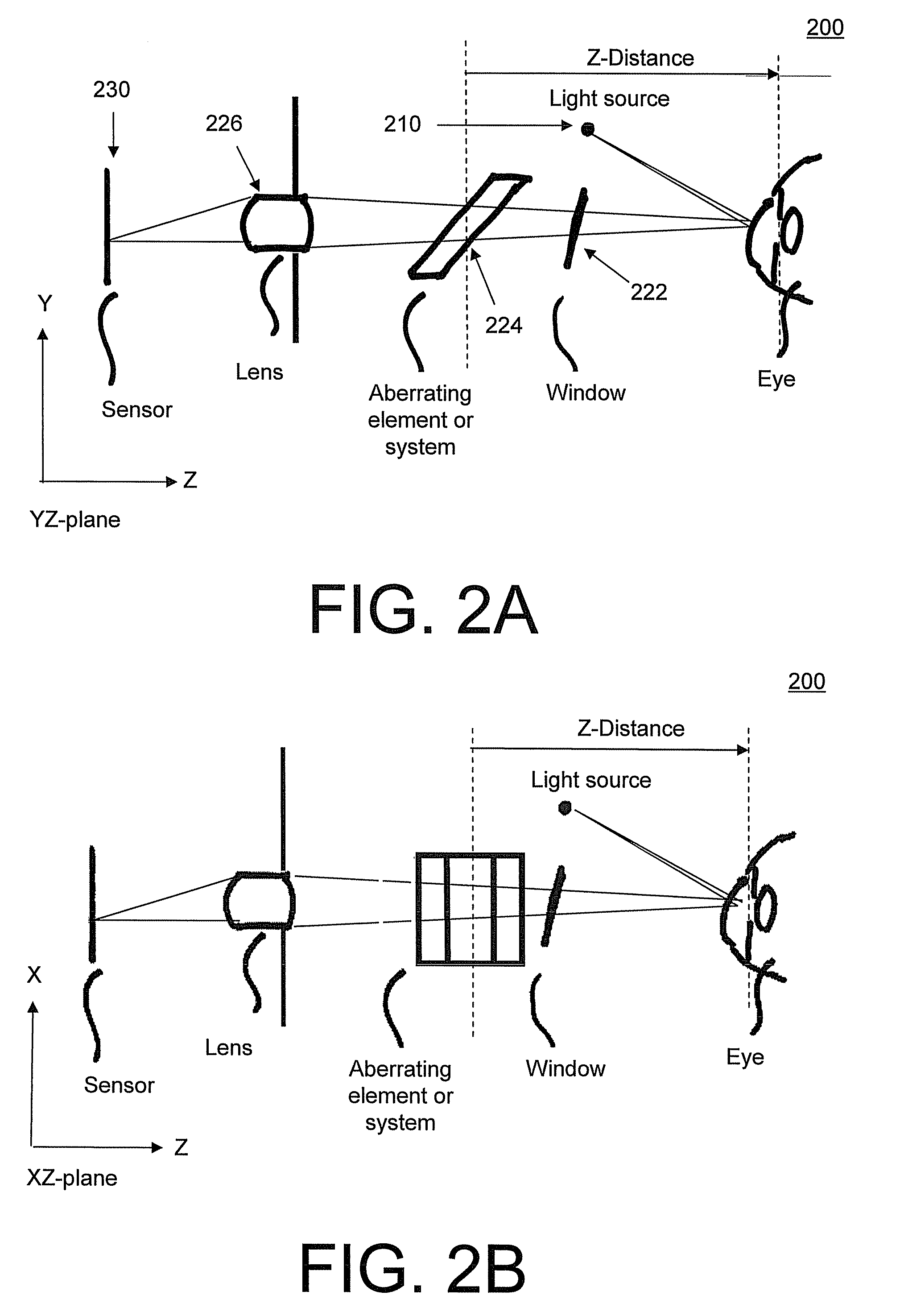
[0021]Disclosed below are systems and methods that utilize an aberration introduced by an optical system to determine the Z-Distance of an optical measurement system to an object under test, such as an eye or other optical system or component.

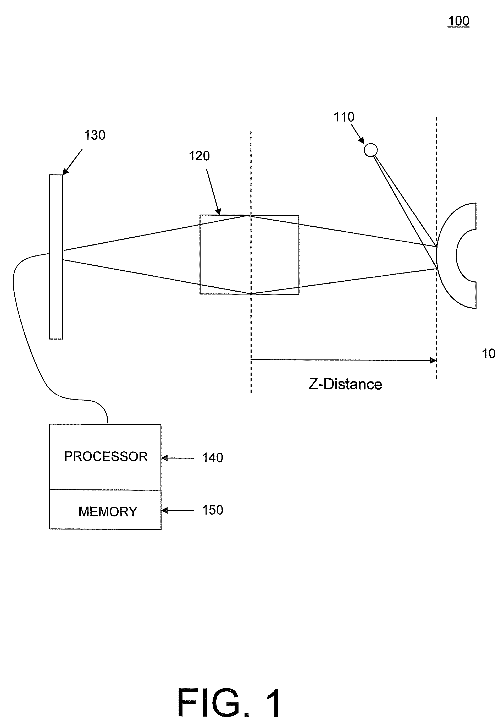
[0022]FIG. 1 illustrates a system 100 for measuring the distance from a reference plane 105 for an optical measurement instrument to a reference plane 15 of an object under test 10.

[0023]System 100 includes an illumination system 110, an optical system 120, an optical sensor 130, a processor 140, and memory 150.

[0024]System 100 may be integrated with an optical measurement instrument, or may be configured as a standalone system that can be employed at the start of an optical measurement to determine the distance from the reference plane 105 for the optical measurement instrument to a reference plane 15 of object under test 10 (hereinafter referred to as “the Z-Distance”) to maintain the accuracy of measurements made by the optical measurement i...


PUM


Abstract

Systems and methods for measuring a distance from a reference plane of an optical measurement instrument to a reference plane of an optical device under test are disclose. In one embodiment a system for measuring this distance includes an illumination system, an optical system, and optical sensor and a processor. The illumination system is configured or adapted to illuminate the object under test. The optical system is configured or adapted to receive light from the object under test and to produce an aberrated image. The optical sensor is configured or adapted to receive and sense the aberrated image. The processor determines the distance from the reference plane of the optical measurement instrument to the reference plane of the optical device based on an aspect of the aberrated image sensed by the optical sensor.

Description

CROSS-REFERENCES TO RELATED APPLICATIONS[0001]This patent application claims priority under 35 U.S.C. §119 of U.S. provisional patent application 60 / 857,776 filed on 9 Nov. 2006, the entirety of which is hereby incorporated by reference for all purposes as if fully set forth herein.BACKGROUND AND SUMMARY[0002]1. Field[0003]This invention relates generally to the field of optical measurement instruments, such as eye examination instruments, and more particularly an apparatus and method for measuring or computing the distance from an object under test (e.g., an eye) to an optical or mechanical reference plane of a measurement instrument.[0004]2. Description[0005]Optical measurement instruments, such as instruments which measure the optical properties of the human eye, rely on the correct working distance being set between a reference plane of the instrument and a reference plane of the object being measured, so that the best possible imaging conditions are met, resulting in the highes...

Claims


Application Information

Patent Timeline
Patent Type & Authority Patents(United States)
IPC IPC(8): A61B3/14A61B3/10A61B3/00
CPCA61B3/1015G01B11/026G01M11/0221A61B3/1005
Inventor BAER, C. DAVIDNEAL, DANIEL R.COPLAND, RICHARD JAMESNEAL, DAVID AUSTIN
Owner AMO DEVMENT
Why Eureka
Try Eureka