Commercial low cost, high efficiency motor-generator

a high-efficiency, motor-generator technology, applied in the direction of windings, magnetic circuit rotating parts, magnetic circuit shapes/forms/construction, etc., can solve the problems of insufficient efficiency of induction motors, and insufficient high-efficiency induction motors. achieve the effect of low cost, high efficiency and high efficiency

Inactive Publication Date: 2011-02-15
REVOLUTION ELECTRIC MOTOR
View PDF15 Cites 39 Cited by
  • Summary
  • Abstract
  • Description
  • Claims
  • Application Information

AI Technical Summary

Benefits of technology

[0008]The invention provides a lower cost, high efficiency motor-generator. The motor-generator achieves both high efficiency and lower costs by utilizing an air core topology with a special low cost armature winding construction that is more easily and rapidly wound and assembled.
[0009]The motor-generator has a rotor that rotates about an axis of rotation, and a stator that is stationary and magnetically interacts with the rotor. The rotor is comprised of two spaced apart rotor portions that define therebetween an armature airgap in which a stationary aircore armature is located. Magnetic poles on the rotor portions drive magnetic flux across the armature airgap and through the armature. The rotor portions provide a low reluctance, high efficiency magnetic flux path for linking the magnetic flux traversing back and forth across the air gap. The rotor portions are preferably constructed of ferromagnetic material, such as steel, which reduces the circumferential reluctance of the flux path and increases the total flux density, power capability, and efficiency.
[0010]It should be noted that in the past, some motor-generators for unique applications have been construction using a single rotor surface acting on a single side of an air core armature. Such designs provide the benefits of simplified assembly and can provide acceptable performance for some applications, especially high speed ones where only a low magnetic flux density is needed for production of high power due to the high operating speed. However, for maximized power capability and efficiency per cost in accordance with this invention, a split rotor is used, enclosing an air core armature on both sides. This is especially applicable for low speed and very cost sensitive applications typical of induction motors.

Problems solved by technology

Electric motors consume more than half of all electrical energy used in most countries.
Unfortunately, induction motors do not provide the highest efficiency.
In such applications, the annual electricity consumption costs can be several times greater than the acquisition cost of the motor.
Unfortunately, conventional brushless permanent magnet motors are much more expensive than induction motors.
They also do not always provide a great enough increase in efficiency and energy savings to justify the increased cost and make them an economically viable alternative, except where the functional benefits of brushless permanent magnet motor necessitate their use.
Despite their potential for increased efficiency, air core permanent magnet brushless motors utilize more magnet material and require an armature that is more difficult, time consuming and costly to construct.
In addition, some constructions can also result in increased armature losses, reducing the potential energy efficiency gains.
For these reasons, such motors have not been widely used in commercial applications for replacement of induction motors.

Method used


Image

  • Commercial low cost, high efficiency motor-generator
  • Commercial low cost, high efficiency motor-generator
  • Commercial low cost, high efficiency motor-generator

Examples


Embodiment Construction

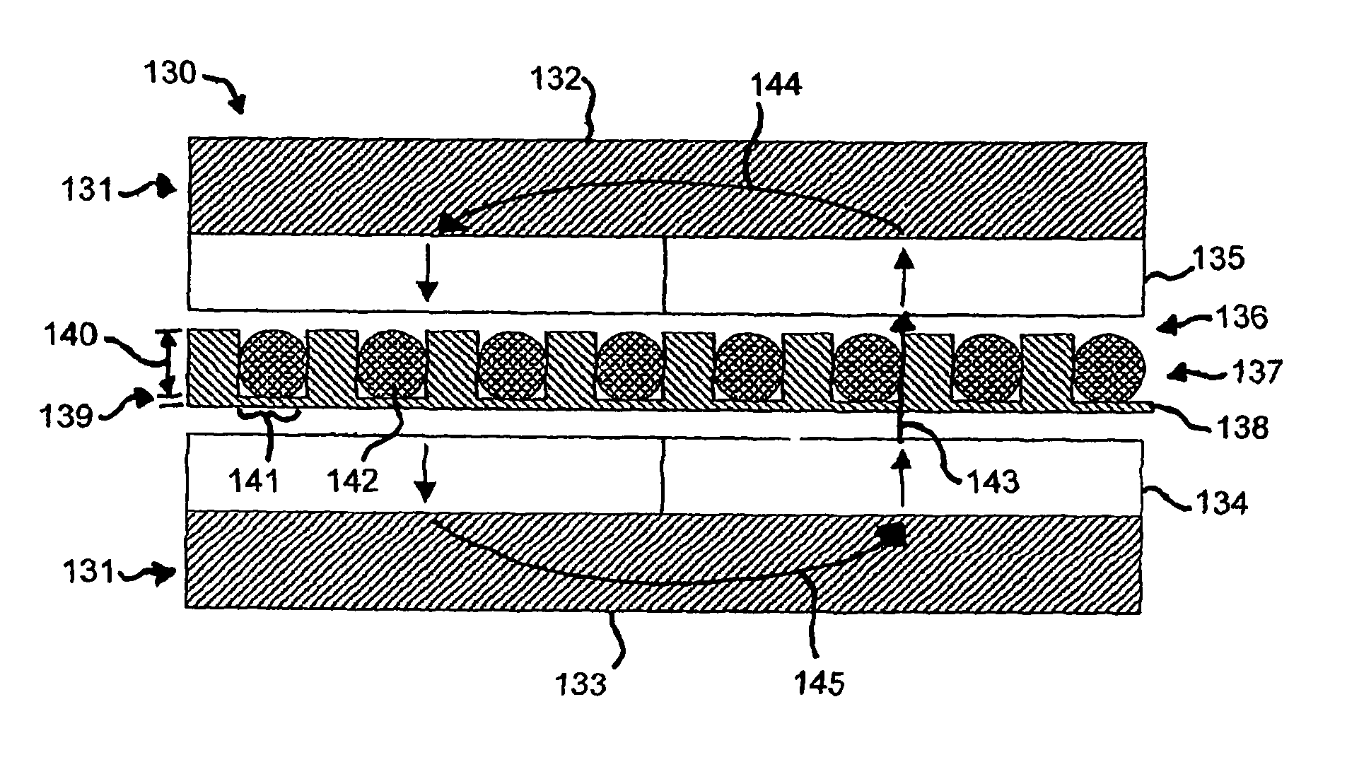
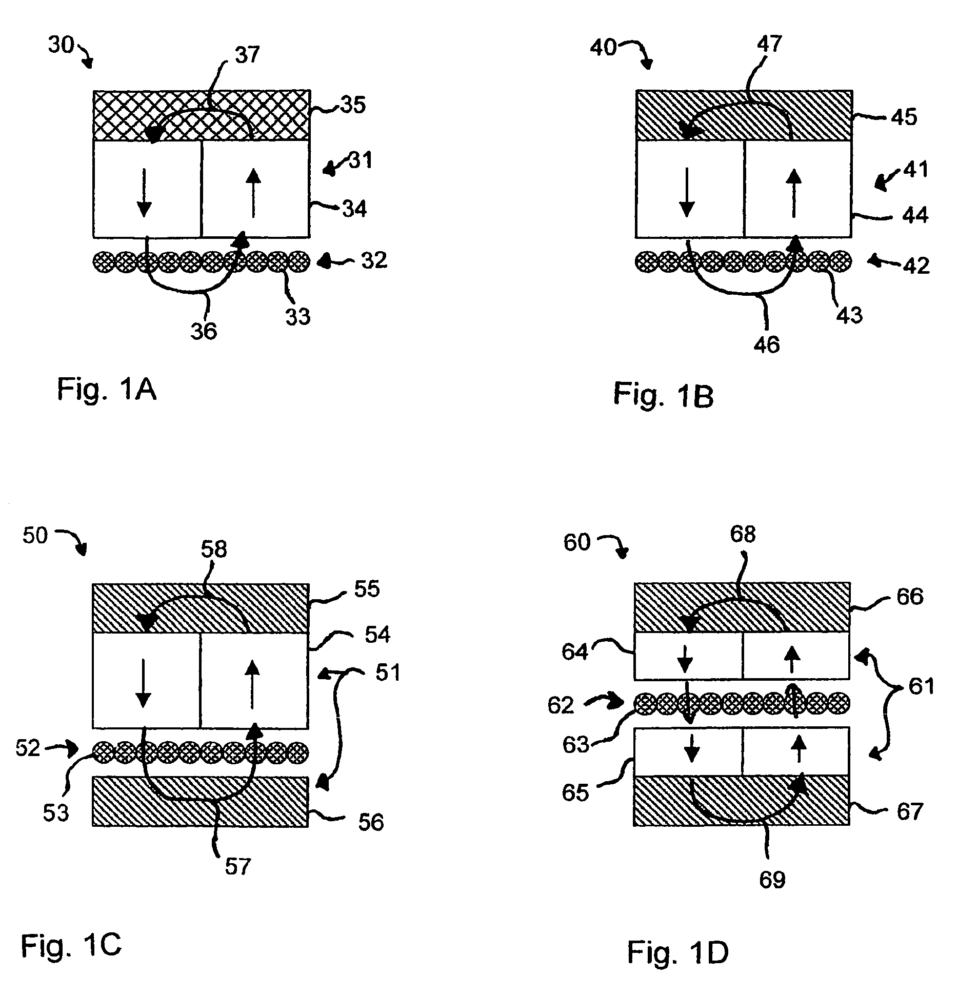
[0071]Turning to the drawings, wherein like reference characters designate identical or corresponding parts, four different magnetic configurations for air core motor-generators are shown in FIGS. 1A-1D for comparison. FIG. 1A shows a small portion of a motor-generator 30 with rotor 31 and stator 32. The stator 32 is comprised of electrical armature windings 33 in close proximity to the rotor 31 for conversion of energy. The rotor 41 comprises alternating polarity magnets 34 attached to a lightweight non-magnetic rotor portion 35. The rotor rotates relative to the stationary stator so, in operation, the magnets 34 pass laterally across the windings 33 in a direction perpendicular to the length of the wire and parallel to the plane in which the wire lies. The magnets 34 drive flux in a loop 36 through the windings 33 and back again around the loop 37 through the rotor portion.

[0072]A motor-generator 40 shown in FIG. 1B has a rotor 41 rotating relative to a stationary stator 42. The s...


PUM

PropertyMeasurementUnit
diameteraaaaaaaaaa
electricalaaaaaaaaaa
rotary mechanical energyaaaaaaaaaa

Abstract

A motor-generator includes a rotor that rotates about an axis of rotation, and a stator that is stationary and magnetically interacts with the rotor. The rotor is constructed of two spaced apart rotor portions having magnetic poles that drive magnetic flux across an armature airgap formed therebetween. An armature, located in the armature airgap, has a substantially nonmagnetic and low electrical conductivity form onto which wire windings are wound. The form has a free end that extends inside the rotor, and a support end that attaches to the stationary portion of the motor-generator. The form is constructed with a thin backing portion and thicker raised portions extending from the backing portion in the direction of the magnetic flux. The wire windings have multiple individually insulated conductor wire. The conductors of a single wire are electrically connected together in parallel and electrically insulated between each other along their length inside the armature airgap. The wire windings are wound on to the form by inserting the wire to lie between the raised portions; the form provides position location and support for the wire windings during the winding process, and subsequently reacts the electromagnetically induced torque on the windings to the stationary portion of the motor-generator through the support end of the form and prevents the windings from contacting the rotor portions during rotation of the rotor.

Description

[0001]This is related to U.S. Provisional Application Nos. 60 / 553,298 filed on Mar. 14, 2004 and 60 / 602,948 filed on Aug. 19, 2004, and to PCT Application No. PCT / US2005 / 008618 filed on Mar. 14, 2005, which was published as International Publication No. WO 2005 / 089327 on Sep. 29, 2005, all under the title “Commercial Low Cost, High Efficiency Motor-Generator.[0002]This invention pertains to electrical machines for converting between electrical and mechanical energy, and more particularly to a low cost, high efficiency motor-generator having a special low cost armature winding construction that very high efficiency and is easily and rapidly wound and assembled.BACKGROUND OF THE INVENTION[0003]Electric motors consume more than half of all electrical energy used in most countries. Currently, the majority of all motors used are induction motors. Induction motors provide simple and reliable operation and have relatively low costs. Unfortunately, induction motors do not provide the highes...

Claims


Application Information

Patent Timeline
Patent Type & Authority Patents(United States)
IPC IPC(8): H02K3/47H02K3/02H02K16/00H02K21/24
CPCH02K3/47H02K21/24Y10T29/49009
Inventor GABRYS, CHRISTOPHER W.RODGERS, TIMOTHY S.
Owner REVOLUTION ELECTRIC MOTOR
Why Eureka
Try Eureka