
Pulsed radar level detection system using pulse dithering to eliminate inaccuracies caused by tank rattle

a technology of pulse radar and detection system, applied in the direction of level indicators, measurement devices, instruments, etc., can solve the problems of waveform inability to infer any information, tank rattle can have a disastrous effect on pulse radar level measurement, and problems such as problems such as problems, to achieve the effect of minimizing inaccuracies, minimizing tank rattle, and minimizing inaccuracy

Inactive Publication Date: 2011-02-15
AMETEK MAGNETROL USA LLC
View PDF7 Cites 11 Cited by
  • Summary
  • Abstract
  • Description
  • Claims
  • Application Information

AI Technical Summary

Benefits of technology

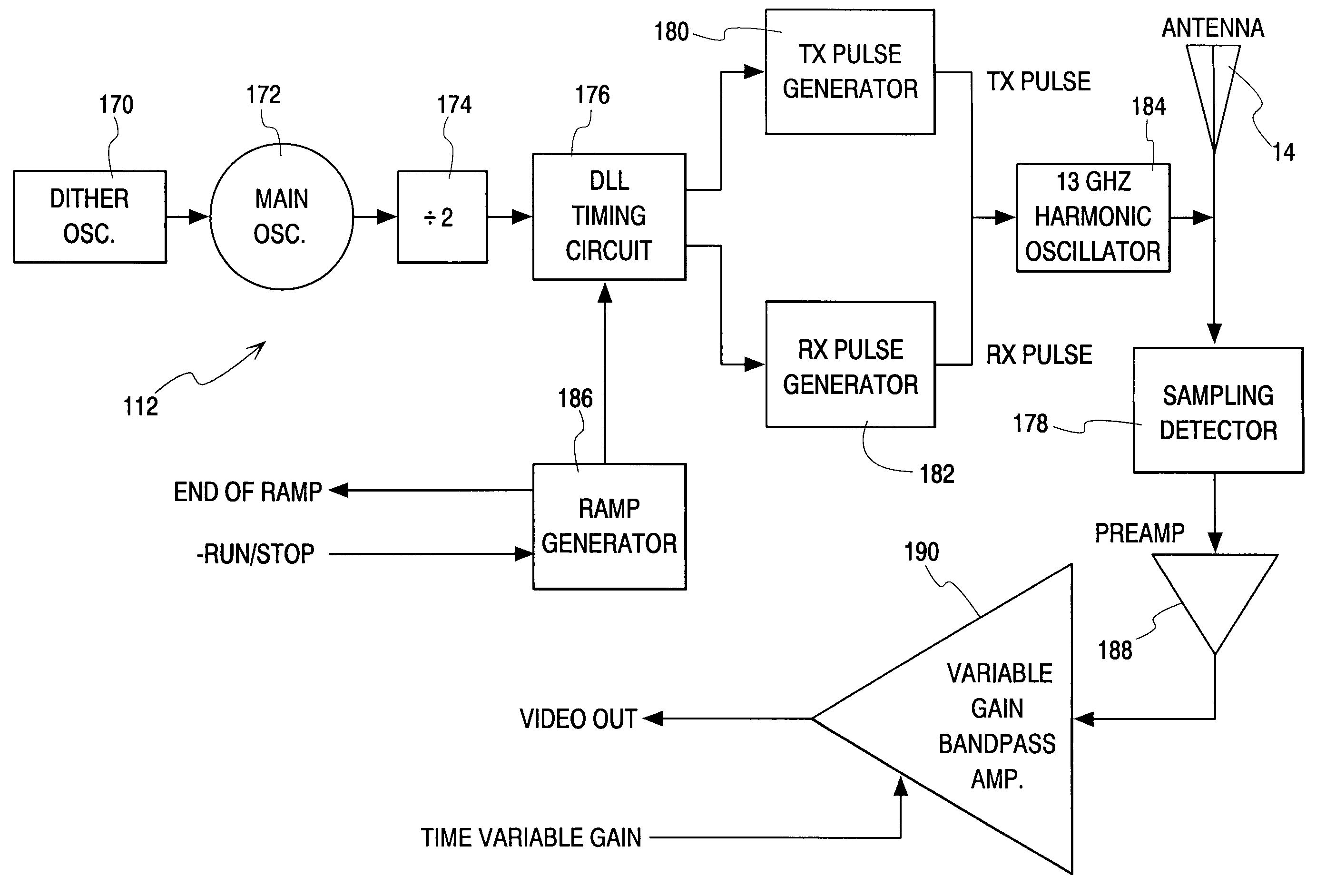
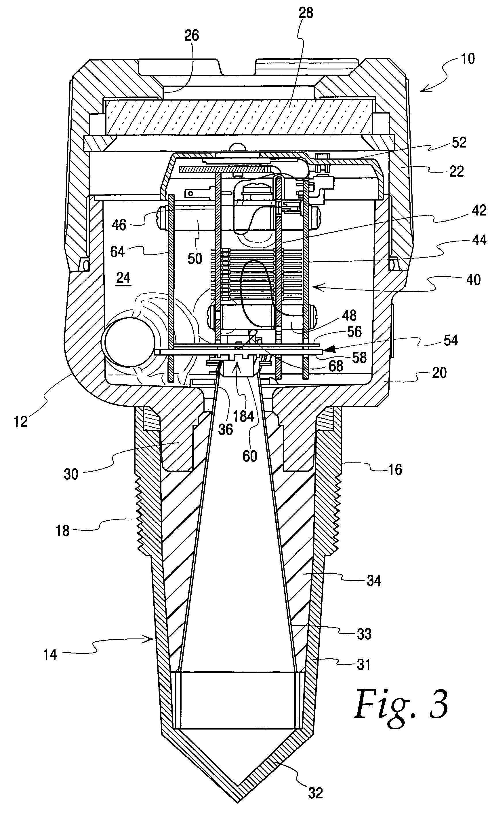
"The invention is an improved through air radar process control instrument that dithers timing between transmitted pulses to minimize inaccuracies caused by tank rattle. The instrument includes a housing, an antenna, a process adaptor for securing the instrument to a closed tank, a control for generating and receiving a high frequency signal, an equivalent time sampling circuit with a main oscillator and a noise generator, and a radiating element. The noise generator includes a dither oscillator that generates a noisy square wave to randomly modulate timing of the main oscillator. The timing circuit includes a delay lock loop and a sampling detector to perform the function of equivalent time sampling. The antenna includes a horn antenna. The method of using the instrument involves securing the sensor to a closed tank and generating a high frequency signal with precise timing between transmitted and sample pulses. The noise generator provides dithering of transmit pulses of different cycles to minimize inaccuracies caused by tank rattle. The technical effects of the invention include improved accuracy and reliability of tank level measurement and minimization of tank rattle inaccuracies."

Problems solved by technology

Problems can arise when attempting to measure the level in an empty or nearly empty tank.
Tank rattle can have a disastrous effect on pulse radar level measurement.
Such a waveform cannot infer any information as to what may be in the tank.

Method used


Image

  • Pulsed radar level detection system using pulse dithering to eliminate inaccuracies caused by tank rattle
  • Pulsed radar level detection system using pulse dithering to eliminate inaccuracies caused by tank rattle
  • Pulsed radar level detection system using pulse dithering to eliminate inaccuracies caused by tank rattle

Examples


Embodiment Construction

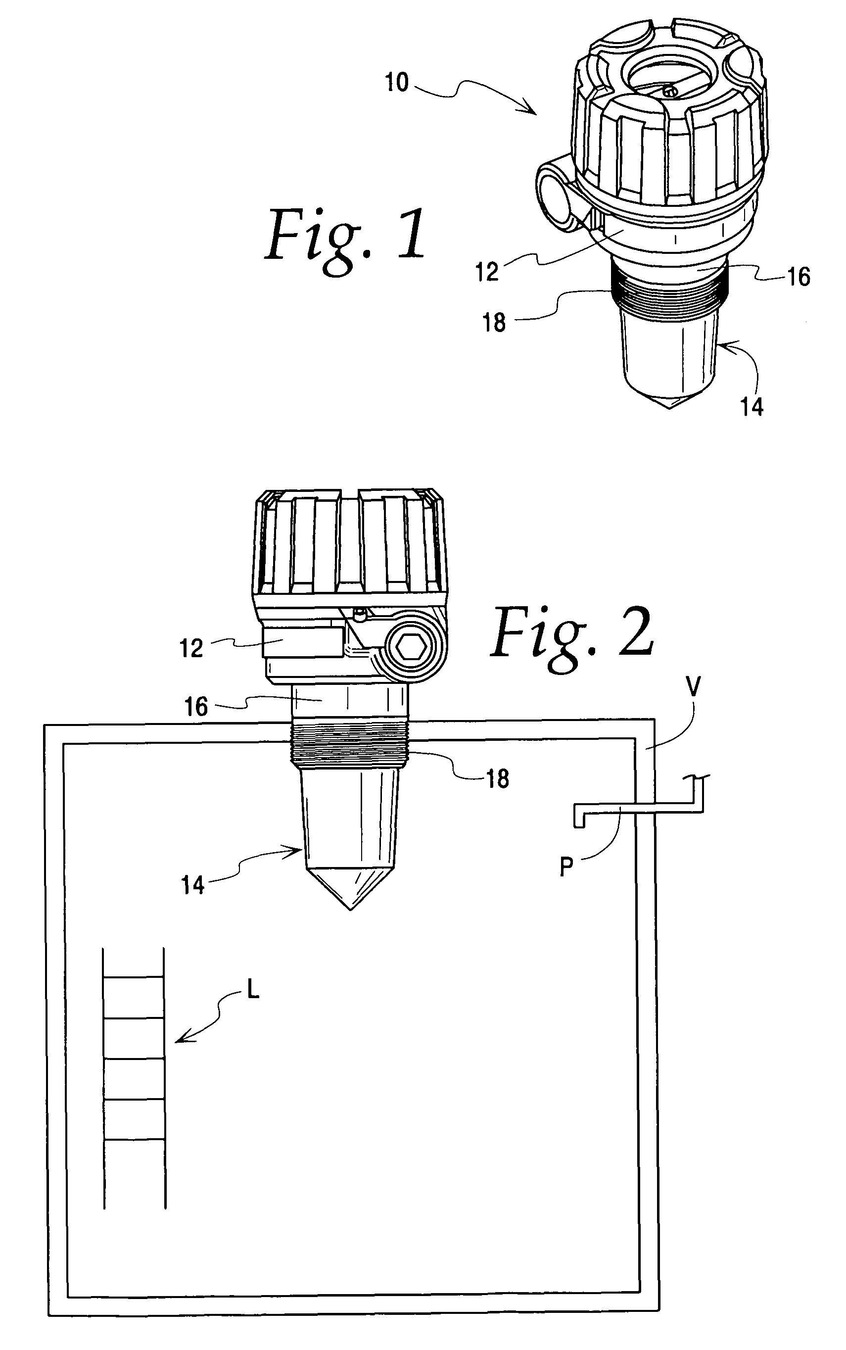
[0028]Referring to FIG. 1, a process control instrument 10 according to the invention is illustrated. The process control instrument 10 uses micro power impulse radar (MIR) in conjunction with equivalent time sampling (ETS) and ultra-wideband (UWB) transceivers for measuring a level using time domain reflectometry (TDR). Particularly, the instrument 10 uses through air radar for sensing level.

[0029]In conventional radar systems, the timing between pulses, the PRF, is usually generated by an accurate, repetitive time base such as a crystal oscillator. When the timing between successive PRF cycles is highly accurate, i.e., correlated, the system is unable to discern between echoes from the current transmitted pulses and those that rattle in the tank long enough to be detected in a subsequent PRF cycle. The instrument 10 solves the problem of tank rattle by randomizing, or “dithering” the timing between successive transmitted pulses, while maintaining precise timing between transmit pu...


PUM


Abstract

A through air level measurement instrument for use in minimizing tank rattle comprises a housing and an antenna secured to the housing. A process adaptor is associated with the antenna and the housing for securing the instrument to a closed tank with the antenna directed into an interior of the closed tank. A control in the housing generates and receives a high frequency signal using an electromagnetic radiating element proximate the antenna. The control comprises an equivalent time sampling circuit including a main oscillator driving a timing circuit controlling timing between transmitted and sample pulses. A noise generator is operatively associated with the main oscillator to randomly modulate timing of the main oscillator. The control minimizes inaccuracies caused by tank rattle.

Description

CROSS REFERENCE[0001]There are no related applications.FIELD OF THE INVENTION[0002]This invention relates to a process control instrument and more particularly, to a through air radar level measurement process control instrument.BACKGROUND OF THE INVENTION[0003]Industrial processes often require measuring the level of liquid or other material in a tank. Many technologies are used for level measurement. With contact level measurement some part of the system, such as a probe, must contact the material being measured. With non-contact level measurement the level is measured without contacting the material to be measured. One example is non-contact ultrasound, which uses high-frequency sonic waves to detect level. Another example is use of high-frequency or microwave RF energy. Microwave measurement for level generally uses either pulsed or frequency modulated continuous wave (FMCW) signals to make product level measurements. This method is often referred to as through air radar. Throug...

Claims


Application Information

Patent Timeline
Patent Type & Authority Patents(United States)
IPC IPC(8): G01S13/08
CPCG01F23/284
Inventor FLASZA, MICHAEL D.
Owner AMETEK MAGNETROL USA LLC
Learn More