Engine

a technology of engine and turbine blade, which is applied in the direction of engines/engines, combination engines, mechanical equipment, etc., can solve the problems of significant impact damage or long-term wear of engines, the turbine machinery of engines, and being very exposed to debris, bird and other particulate matter, etc., and achieves the effect of not being able to provide such a curved inlet duct and being convenient to us

Active Publication Date: 2011-02-22
ROLLS ROYCE PLC
View PDF19 Cites 23 Cited by
  • Summary
  • Abstract
  • Description
  • Claims
  • Application Information

AI Technical Summary

Benefits of technology

[0015]Preferably, the rotor propels a portion of the inlet flow into the thrust core to provide a boost to core pr

Problems solved by technology

A significant problem with these gas turbine engines is ingress of debris and birds as particulate matter which will impinge upon the blades of the compressor stage(s) and subsequent parts of the engine's core machinery with possibly significant impact damage or long term wear problems.
Furthermore, it will be understood that a propeller located rearward will result in the inlet for the thrust core, that is to say the turbine machinery of the engine, being very exposed to debris, bird and other particulate matter.
Howe

Method used


Image

  • Engine
  • Engine
  • Engine

Examples


first embodiment

[0063]In the variable geometry 70 depicted in FIG. 3 a bypass chute 33 incorporates a wall portion 36 which is hinged about a pivot 37 to enable variation in the cross sectional area of the bypass chute 33. The wall portion 36 moves inwardly and outwardly to vary the flow area of the chute 33 to an extent dependent upon operational requirements but highlighted by broken line 38 in FIG. 3. Generally, an actuator 39 acts through a unison ring 40 such that, as will be described later, all of the bypass chutes 33 extending to exits 41 have their wall portions 36 deflected equally for symmetry and load distribution about the annulus of the engine.

[0064]It is well known that an aircraft and its engines have a number of operating conditions, which are commonly referred to as take-off, climb, cruise and approach or descent. Generally, the engines are at a maximum output at take-off and parts of the climb and output then reduces at cruise to maintain a near constant airspeed. On descent the ...

second embodiment

[0067]In the variable geometry 70 depicted in FIG. 3, the bypass chute 33 incorporates a slidable door 43 generally located at the exit plane 41. The slidable door 43 slides in the direction of arrowhead X to reduce the exit aperture area dependent on operational circumstances and advantageously minimise the aerodynamic discontinuity of the bypass chute 33. An actuator 139 is connected to the slidable door 43 to enable its operation. The door is movable between a fully open position as shown and a fully closed position.

[0068]The slidable door 43 is capable of varying the flow area of the chute 33 in a similar manner to the first embodiment. The slidable or translating door 43 may be either one of a plurality of doors positioned around the engine casing 34 or may be annular or part annular.

[0069]Where it is desirable for the bypass chute 33 to be completely closed, debris and particulate matter may build up within the bypass chute 33 and later released by displacement of the wall por...


PUM


Abstract

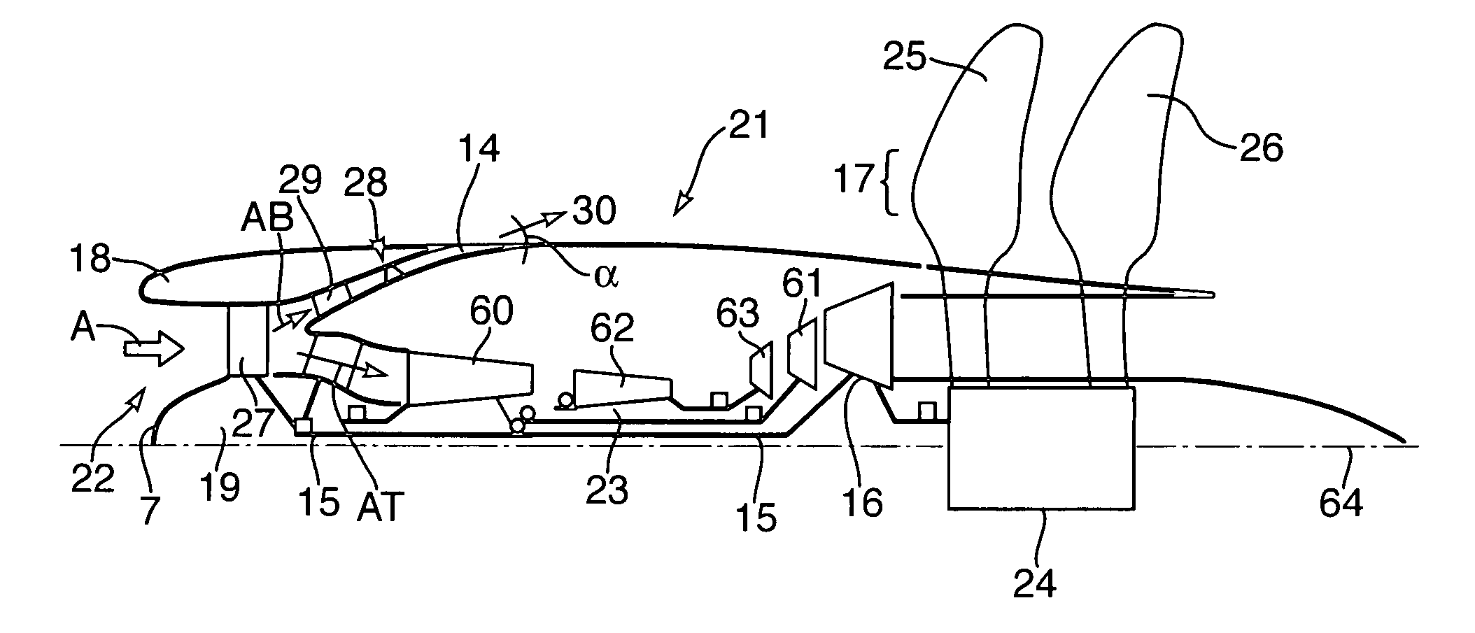
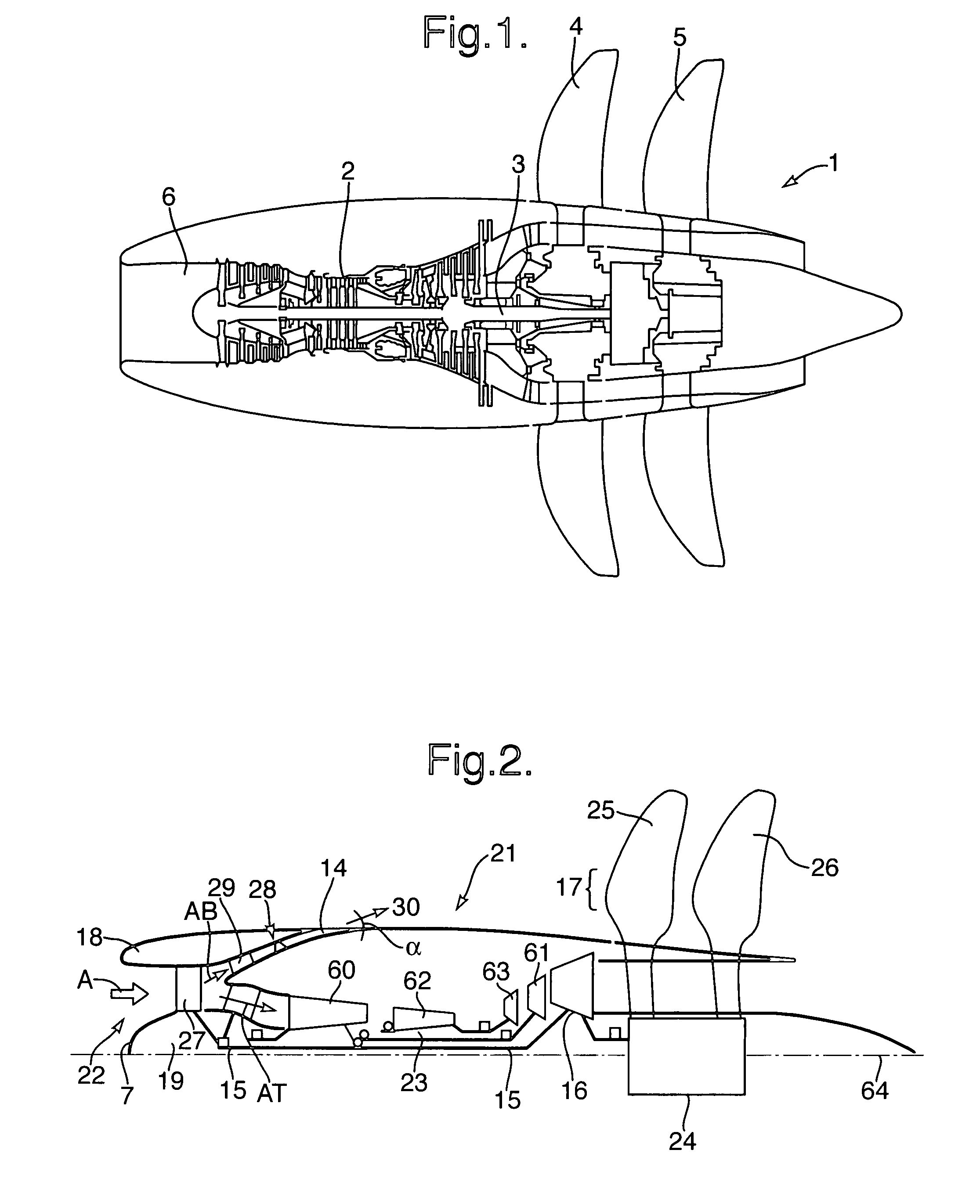
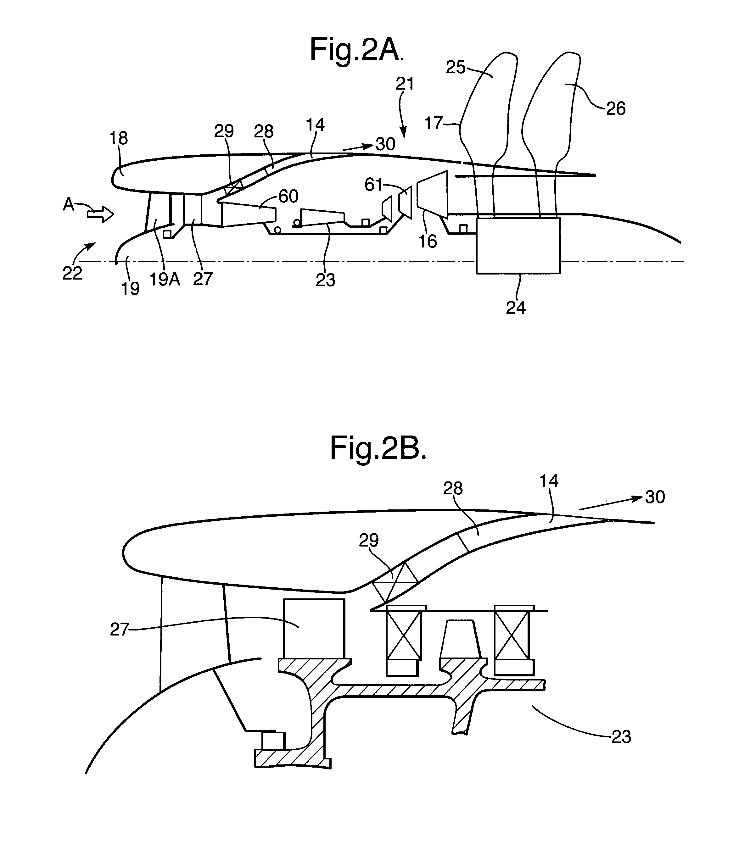
In prop fan and contra fan gas turbine engines particularly utilized with regard to pusher configurations towards the aft of an aircraft, there is a significant problem with regard to debris and bird strikes resulting in particulate matter which may damage the engine thrust core. By providing an inlet rotor which fragments and creates a centrifugal aspect to the inlet flow, particulate matter can be directed to a bypass chute normally in the form of an annular section extending into a number of chute exits. In such circumstances, the particulate matter is removed continuously from the inlet flow and the chutes are normally angled to project any particulate matter towards propellers of the engine at robust positions.

Description

BACKGROUND[0001]1. Field of the Invention[0002]The present invention relates to an engine and more particularly to gas turbine engines in which the gas turbine drives a shaft on which a propeller or unducted fan is provided for propulsion.[0003]2. Description of Related Art[0004]Operation of gas turbine engines is well known. In some situations it is preferable to couple the propulsion power of that gas turbine engine through a shaft to drive an unducted fan, open rotor or prop for propulsion. These engine configurations are referred to as propfans or contra-rotating fans and utilise a relatively low specific thrust engine. It is also known there are advantages with regard to positioning such propfans and contra-rotating fans towards the rear of an aircraft in a pusher or aft fan configuration.[0005]A significant problem with these gas turbine engines is ingress of debris and birds as particulate matter which will impinge upon the blades of the compressor stage(s) and subsequent par...

Claims


Application Information

Patent Timeline
IPC IPC(8): F02G3/00
CPCF02C7/052
Inventor RICHARDS, MARTYN
Owner ROLLS ROYCE PLC
Why Eureka
Try Eureka