
Electronic device with waterproof structure and fabrication method thereof

Inactive Publication Date: 2008-09-04
DELTA ELECTRONICS INC
View PDF8 Cites 9 Cited by
  • Summary
  • Abstract
  • Description
  • Claims
  • Application Information

AI Technical Summary

Benefits of technology

[0009]It is an object of the present invention to provide an electronic device with a waterproof structure for preventing water or foreign matters from entering the housing structure and facilitating heat dissipation in an active heat-dissipating mechanism.
[0010]Another object of the present invention provides an electronic device with a waterproof structure, in which a protective layer is formed on at least a portion of the electronic components and the electrical trace patterns on the printed circuit board to facilitate dissipating heat and withstanding vibration, impact or pressure.
[0011]Another object of the present invention provides a process of fabricating an electronic device with a waterproof structure in a simple and cost-effective manner.
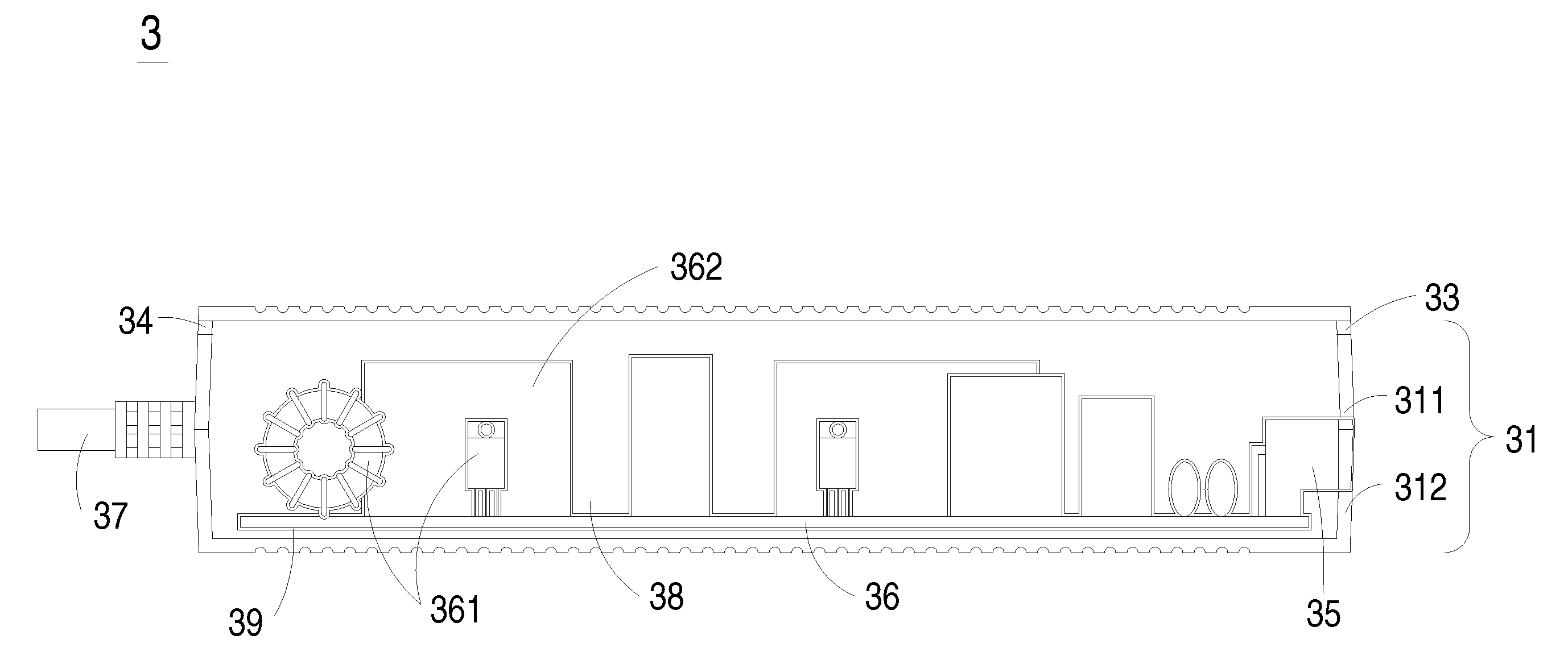
[0012]In accordance with an aspect of the present invention, there is provided an electronic device with a waterproof structure. The electronic device includes a housing structure, a printed circuit board and a protective layer. The housing structure includes a receptacle, a first opening and a second opening. The printed circuit board is disposed within the receptacle and includes plural electronic components and electrical trace patterns thereon. The protective layer is formed on at least a portion of the electronic components and the electrical trace patterns to protect the printed circuit board from moisture attack.

Problems solved by technology

As the volume of the electronic device is decreased, the problem associated with heat dissipation becomes more serious.
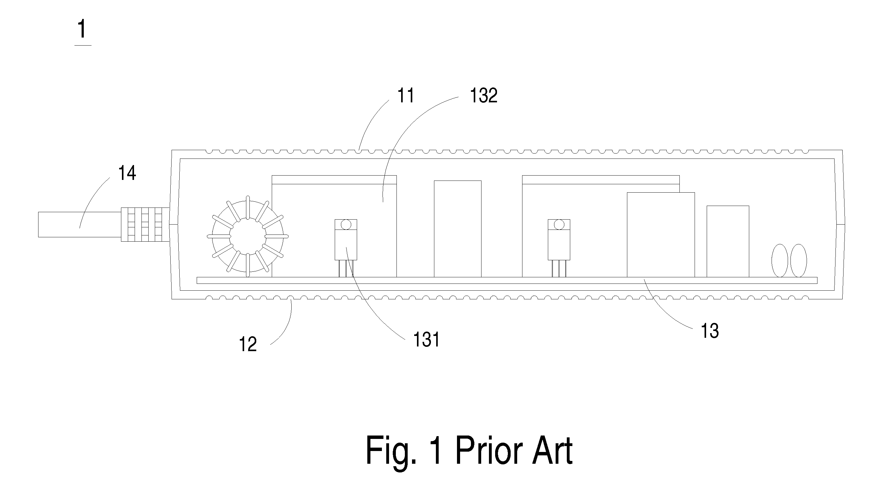
When the power adapter operates, the electronic components on the printed circuit board thereof may generate energy in the form of heat, which is readily accumulated within the receptacle and usually difficult to dissipate away.
If the power adapter fails to transfer enough heat to ambient air, the elevated operating temperature may result in damage of the electronic components, a breakdown of the whole power adapter or reduced power conversion efficiency.
Since the power adapter 1 is developed toward minimization and designed to have higher power, the passive heat-dissipating mechanism described above is not satisfactory.
Under this circumstance, the power adapter 1 fails to be operated in humid surroundings or outdoors due to the poor waterproof properties.
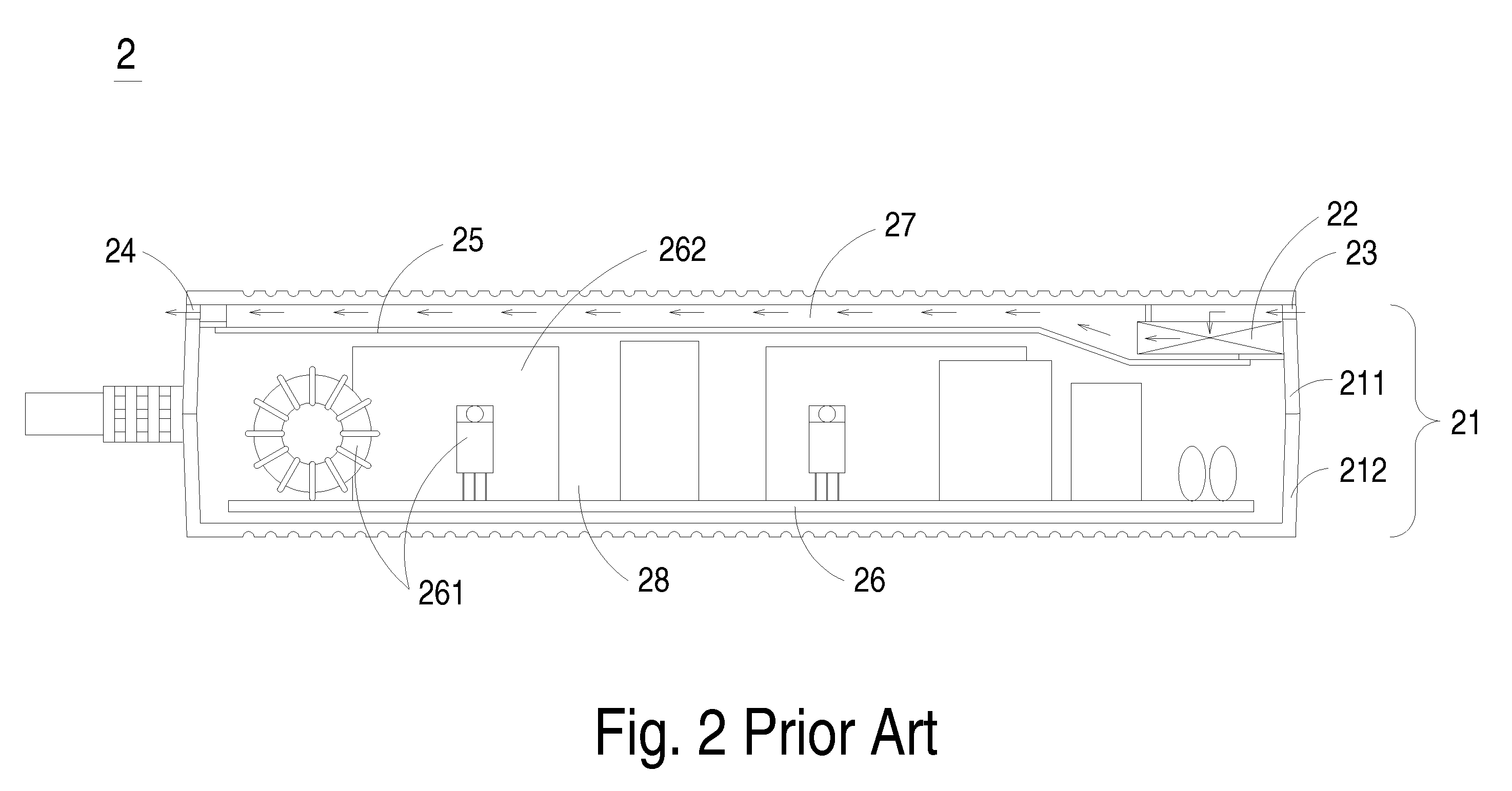
If the power adapter 1 having the active heat-dissipating mechanism is used in the humid surroundings or outdoors, the electronic components may be damaged or shorted in case of contacting with water.
The foreign matters or dust may result in a continuity failure or damage of the printed circuit board, and thus the whole computer or power supply apparatus may be short-circuited or have a breakdown.
As a consequence, the quality and the reliability of the power adapter 1 are impaired.
Although the waterproof and heat-dissipating structure is effective for preventing water from entering the housing structure and removing heat, there are still some drawbacks.
For example, the waterproof and heat-dissipating structure is complicated and thus not cost-effective.
In addition, since a poor thermally-conductive medium (i.e. air) exists between the spacing structure 25 and the electronic components 261 and / or the heat sinks 262, the heat-dissipating efficiency of such a heat-dissipating mechanism is not satisfied.

Method used


Image

  • Electronic device with waterproof structure and fabrication method thereof
  • Electronic device with waterproof structure and fabrication method thereof
  • Electronic device with waterproof structure and fabrication method thereof

Examples


Embodiment Construction

[0020]The present invention will now be described more specifically with reference to the following embodiments. It is to be noted that the following descriptions of preferred embodiments of this invention are presented herein for purpose of illustration and description only. It is not intended to be exhaustive or to be limited to the precise form disclosed.

[0021]Referring to FIG. 3, a schematic cross-sectional view of an electronic device with a waterproof structure according to a preferred embodiment of the present invention is illustrated. The electronic device 3 is for example a power supply apparatus or a power adapter. The power adapter 3 comprises a housing structure 31, a first opening 33, a second opening 34, a power input member 35, a printed circuit board 36 and a power output member 37. The housing structure 31 includes an upper housing 311 and a lower housing 312. A receptacle 38 is defined between the upper housing 311 and the lower housing 312 for accommodating the pr...


PUM

PropertyMeasurementUnit
Poweraaaaaaaaaa
Water resistanceaaaaaaaaaa

Abstract

An electronic device with a waterproof structure includes a housing structure, a printed circuit board and a protective layer. The housing structure includes a receptacle, a first opening and a second opening. The printed circuit board is disposed within the receptacle and includes plural electronic components and electrical trace patterns thereon. The protective layer is formed on at least a portion of the electronic components and the electrical trace patterns to protect the printed circuit board from moisture attack.

Description

FIELD OF THE INVENTION[0001]The present invention relates to an electronic device, and more particularly to an electronic device with a waterproof structure. The present invention also relates to a method for fabricating such an electronic device.BACKGROUND OF THE INVENTION[0002]With increasing integration of integrated circuits, electronic devices such as power adapters and power supply apparatuses are developed toward minimization. As the volume of the electronic device is decreased, the problem associated with heat dissipation becomes more serious. Take a power adapter for example. The conventional power adapter comprises an upper housing and a lower housing, which are made of plastic materials and cooperatively defines a receptacle for accommodating a printed circuit board. When the power adapter operates, the electronic components on the printed circuit board thereof may generate energy in the form of heat, which is readily accumulated within the receptacle and usually difficul...

Claims


Application Information

Patent Timeline
IPC IPC(8): H05K1/18
CPCH05K3/284Y10T29/49002H05K2201/09872H05K7/209
Inventor YU, WEN-LUNGLIU, YU-TANG
Owner DELTA ELECTRONICS INC
Learn More