Exhaust casing hub comprising stress-distributing ribs

a technology of exhaust casing and stress-distributing ribs, which is applied in the direction of machine supports, machines/engines, liquid fuel engines, etc., can solve the problems of limited life of current known casings and cost-intensive measures for air companies, and achieve the effect of increasing the life of the exhaust casings

Active Publication Date: 2011-02-22
SN DETUDE & DE CONSTR DE MOTEURS DAVIATION S N E C M A
View PDF11 Cites 35 Cited by
  • Summary
  • Abstract
  • Description
  • Claims
  • Application Information

AI Technical Summary

Benefits of technology

[0005]The subject of the present invention is an exhaust casing hub and an exhaust casing which overcome these disadvantages by making it possible, in particular, to increase the life of the exhaust casings.

Problems solved by technology

However, the currently known casings have a limited life as a result of concentrations of stresses in the cuffs of the hub.
This measure is costly for air companies since it requires them to intervene beneath the wing of the aircraft and to immobilize this aircraft.

Method used


Image

  • Exhaust casing hub comprising stress-distributing ribs
  • Exhaust casing hub comprising stress-distributing ribs
  • Exhaust casing hub comprising stress-distributing ribs

Examples


Embodiment Construction

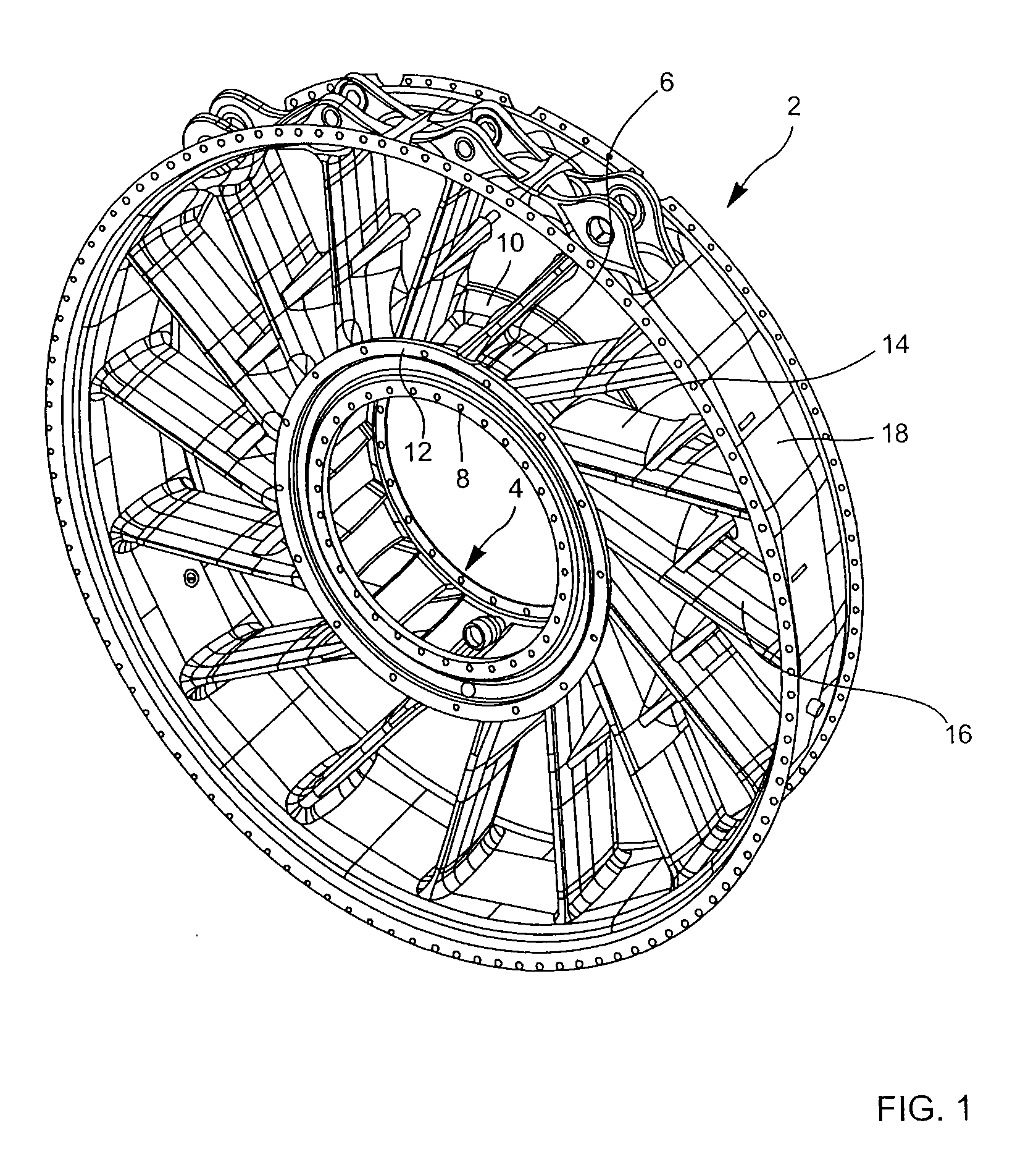
[0016]In FIG. 1, the general reference 2 designates an exhaust casing in accordance with the present invention. This exhaust casing comprises a hub designated by the reference 4. The hub 4 comprises a hub center 6 and, on either side of this hub center 6, an upstream flange 8 and a downstream flange 10 which are terminated by a rim 12. Cuffs 14 are formed on the hub center 6. In the exemplary embodiment represented, the number of these cuffs is sixteen. The hub 4 is a casting. An arm 16 is welded to the end of each of the cuffs 14. There are thus sixteen arms in the exemplary embodiment represented. The circular parts 18, equal in number to the number of arms, are welded to the ends of the arms 16 so as to form a circular shroud which completes the exhaust casing.

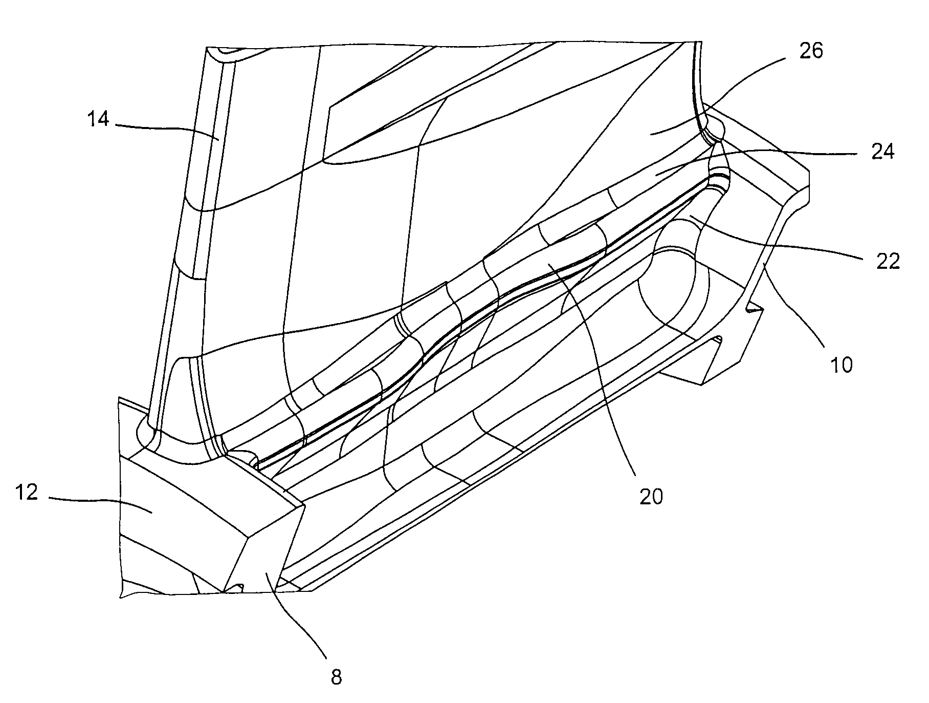
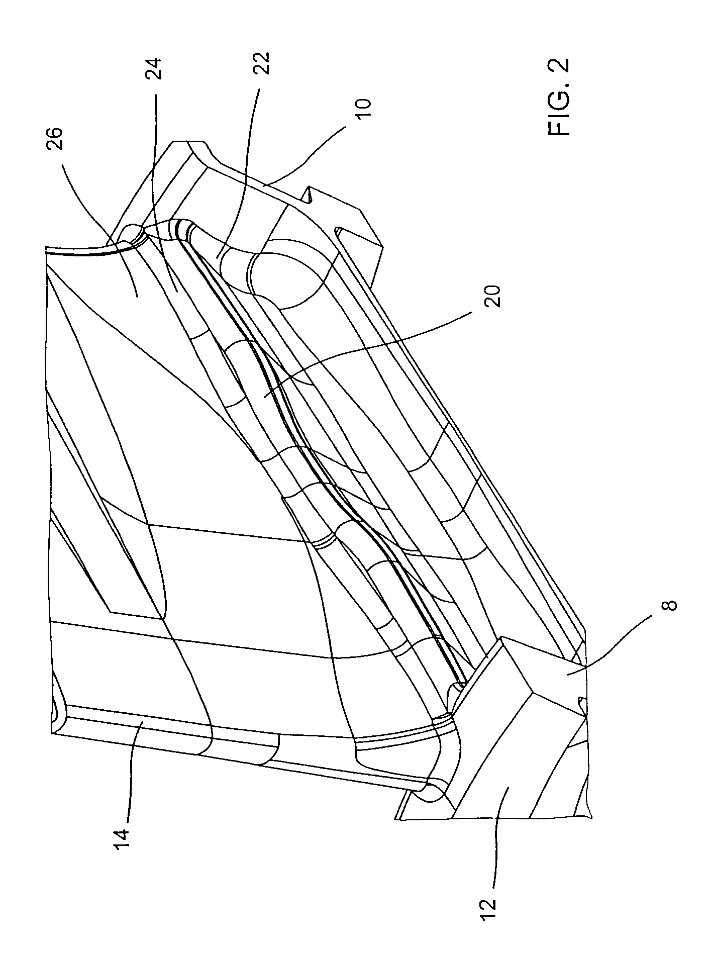
[0017]FIGS. 2 and 3 show a top view and a side view, respectively, of a rib 20 formed in the hub of the exhaust casing represented in FIG. 1. The rib 20 extends from the upstream flange 8 to the downstream flange 10. It is ...


PUM


Abstract

An exhaust casing hub includes a hub center, and an upstream flange and a downstream flange arranged on either side of the hub center. Each flange is terminated by a rim. A plurality of cuffs are arranged on the hub center so as to form an angle from the tangent toward the radial direction of 10° to 80° , preferably 15° to 75°. At least one rib is formed at the base of each cuff below a critical stress region in the cuff. The rib is joined to the downstream flange by a downstream end and to the upstream flange by an upstream end.

Description

BACKGROUND OF THE INVENTION AND DESCRIPTION OF THE PRIOR ART[0001]The invention relates to an equipped hub of an exhaust casing comprising a hub, an upstream flange and a downstream flange arranged on either side of the hub, each flange being terminated by a rim, and a plurality of cuffs arranged on the hub and forming an angle between the tangent and the radial direction.[0002]Aircraft jet engines comprise an exhaust casing situated downstream of the low-pressure turbine. This casing has the function of suspending the engine under the wing, of routing the service tubes and of absorbing the loads in the event of a blade loss.[0003]The exhaust casing is frequently a mechanically welded part made up of a hub comprising substantially radially arranged cuffs and of arms welded to the cuffs. Parts are welded to the ends of the arms to form an outer shroud. Document US 2005 / 026847 describes an exhaust casing of this type.[0004]However, the currently known casings have a limited life as a ...

Claims


Application Information

Patent Timeline
Patent Type & Authority Patents(United States)
IPC IPC(8): F04D29/02
CPCF01D25/30F02C7/00F02C7/20F05D2250/70F05D2260/941
Inventor BADER, VALENTINEMARNAS, LAURENT PIERRE ELYSEE GASTONPOMMIER, NICOLASSCHNELL, CHRISTIAN RENE
Owner SN DETUDE & DE CONSTR DE MOTEURS DAVIATION S N E C M A
Why Eureka
Try Eureka