Method for manufacturing heat dissipator having heat pipes and product of the same

a heat dissipator and heat pipe technology, which is applied in the direction of lighting and heating apparatus, electrical equipment, cooling/ventilation/heating modifications, etc., can solve the problems of heat generation generated by electronic products, inability to distribute heat absorbed by the heat-conducting base, and failure of heat conduction of the heat pipe, so as to avoid the heat from exceeding the workload of single heat pipe and maintain the heat dissipation efficiency of the heat dissipator

Inactive Publication Date: 2011-02-22
GOLDEN SUN NEWS TECHN +1
View PDF11 Cites 10 Cited by
  • Summary
  • Abstract
  • Description
  • Claims
  • Application Information

AI Technical Summary

Benefits of technology

[0008]In view of the above drawbacks, the present invention provides a method for manufacturing a heat dissipator having heat pipes and a product of the same. With a plurality of heat pipes overlapped on the same position, the plurality of heat pipes that are arranged on the same position can absorb the heat at the same time, thereby avoiding the heat from exceeding the workload of single heat pipe and keeping the heat-dissipating efficiency of the heat dissipator.
[0009]The present invention provides a heat dissipator having heat pipes, which includes a heat-conducting base, a first heat pipe and a second heat pipe. The heat-conducting base has an accommodating trough. After the first heat pipe is accommodated in the accommodating trough, it is deformed so as to abut against the inner wall face of the accommodating trough. Further, the second heat pipe and the first heat pipe are provided in the same accommodating trough, and the second heat pipe is overlapped vertically on the first heat pipe. As a result, the second heat pipe is deformed so as to abut against the first heat pipe and the interior of the accommodating trough, thereby enhancing the heat-conducting performance of the heat dissipator.

Problems solved by technology

In addition, the heat generated by these electronic products also increases to a large extent.
However, since the amount of heat generated by the heat-generating element has developed to an unanticipated extent, and the heat capacity of the capillary structure and working fluid within single heat pipe is fixed, excessive heat may cause the working fluid within the heat pipe to be vaporized and thus cannot circulate therein, so that the heat conduction of the heat pipe totally fails.
Although a plurality of sets of heat pipes are provided on one heat dissipator, the heat absorbed by the heat-conducting base cannot be distributed to each heat pipe uniformly, and thus the problem of vaporizing the working fluid within the heat pipe still exists.

Method used


Image

  • Method for manufacturing heat dissipator having heat pipes and product of the same
  • Method for manufacturing heat dissipator having heat pipes and product of the same
  • Method for manufacturing heat dissipator having heat pipes and product of the same

Examples


Embodiment Construction

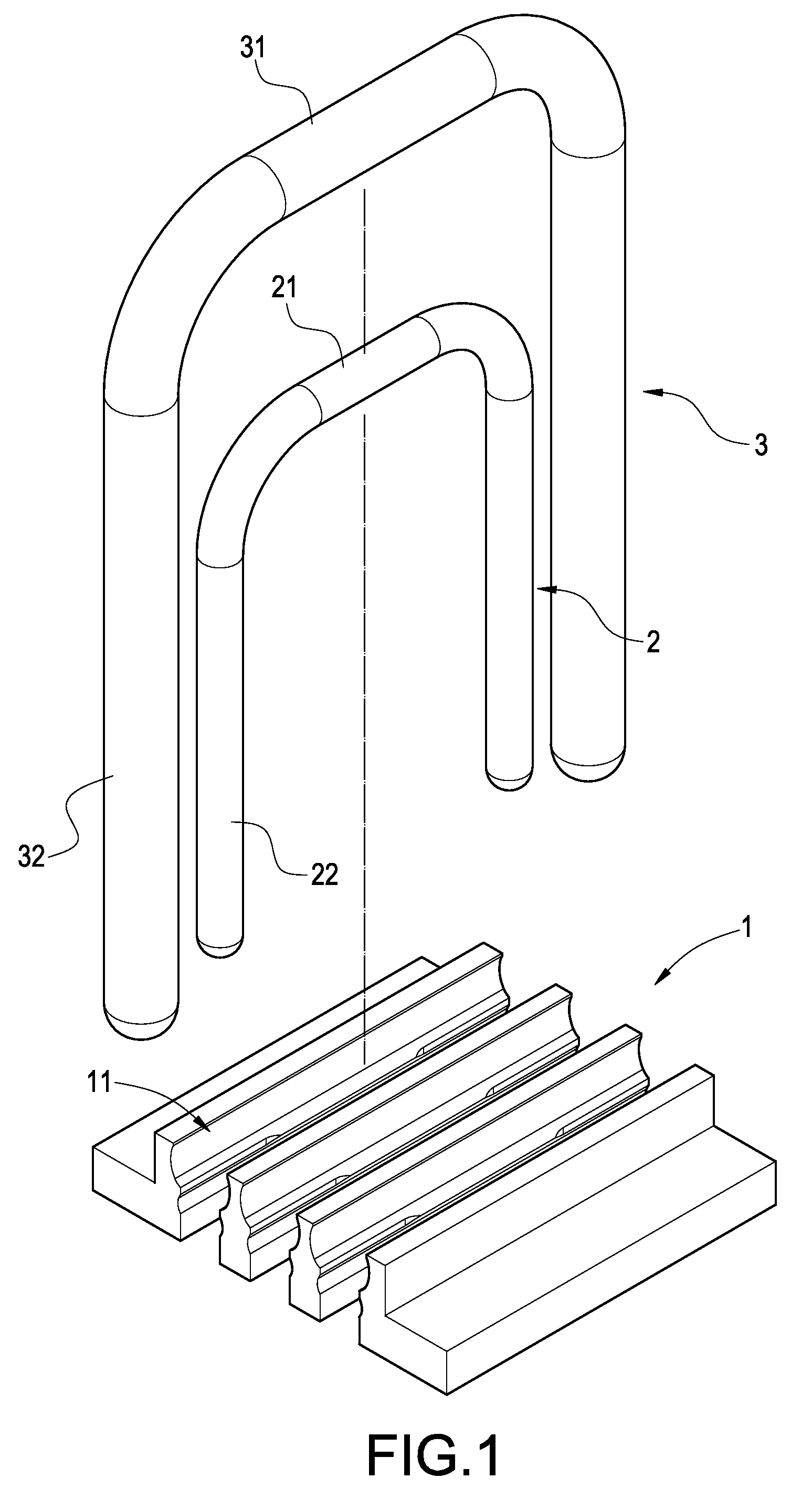
[0019]The technical contents of the present invention will be described with reference to the accompanying drawings.

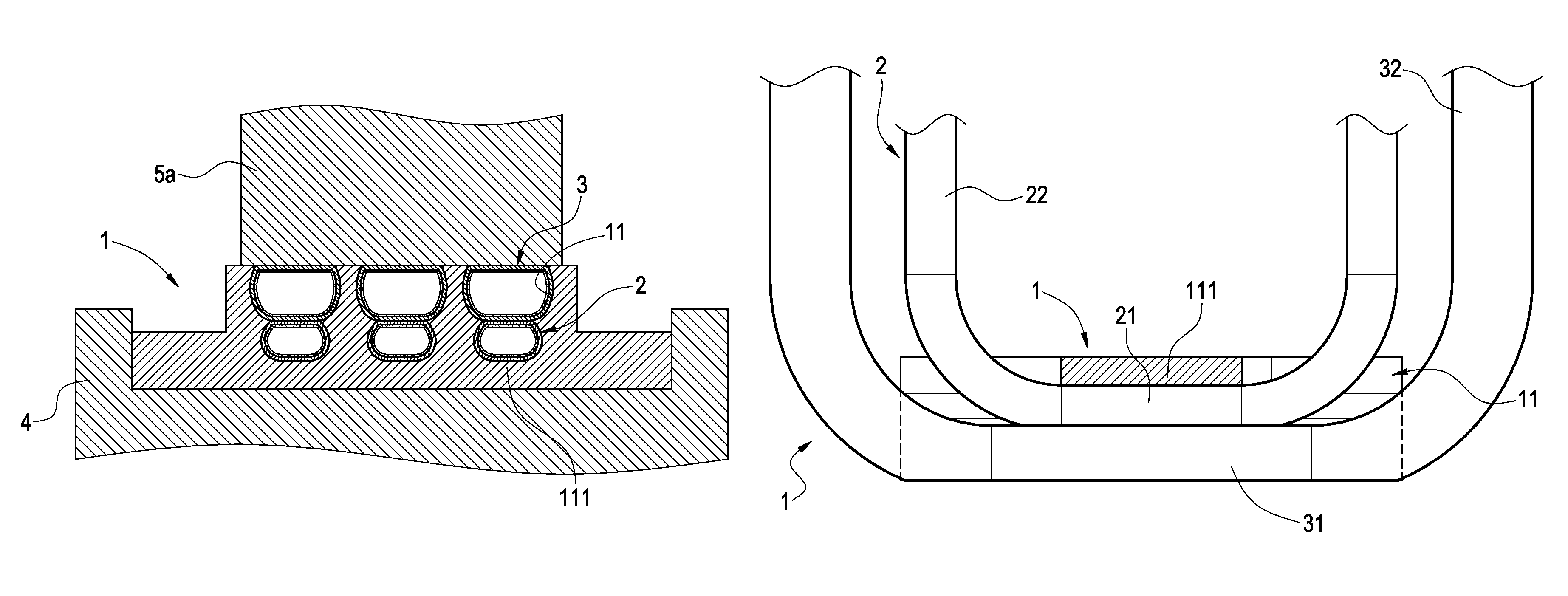
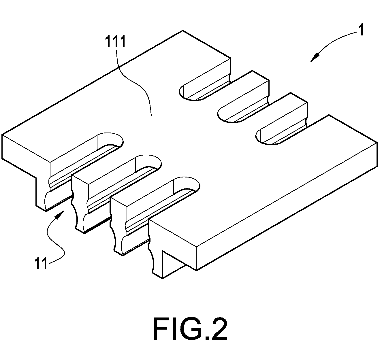
[0020]FIG. 1 is an exploded perspective view of the present invention, and FIG. 2 is a rear view thereof. As shown in these figures, the heat dissipator having heat pipes includes a heat-conducting base 1, a first heat pipe 2 and a second heat pipe 3. The heat-conducting base 1 is made of materials having high heat conductivity. The heat-conducting base 1 is provided thereon with at least one accommodating trough 11. The accommodating trough 11 as a bottom surface defining an abutting section 111, an opening opposite the bottom surface, and side surfaces defining inner wall faces extending therebetween. The first heat pipe 2 is pressed against / contacts the bottom surface / abutting section 111, while the second heat pipe 3 is pressed against the first heat pipe 2 so as to partially cover the first heat pipe 2, such that the first heat pipe 2 is disposed between the botto...


PUM

PropertyMeasurementUnit
heat-conductingaaaaaaaaaa
diameteraaaaaaaaaa
heat-aaaaaaaaaa

Abstract

A heat dissipator having heat pipes includes a heat-conducting base, a first heat pipe and a second heat pipe. The heat-conducting base has an accommodating trough. After the first heat pipe is accommodated in the accommodating trough, it is deformed so as to abut against the inner wall face of the accommodating trough. Further, the second heat pipe and the first heat pipe are provided in the same accommodating trough, and the second heat pipe is overlapped vertically on the first heat pipe. As a result, the second heat pipe is deformed so as to abut against the first heat pipe and the interior of the accommodating trough, thereby enhancing the heat-conducting performance of the heat dissipator.

Description

BACKGROUND OF THE INVENTION[0001]1. Field of the Invention[0002]The present invention relates to a heat-dissipating device, and in particular to a method for manufacturing a heat dissipator having heat pipes and a product of the same.[0003]2. Description of Prior Art[0004]The electronic products of modern technical industries are made more and more precise, and thus the volume thereof is miniaturized. In addition, the heat generated by these electronic products also increases to a large extent. Since excessive heat may affect the working performance and the lifetime of the electronic product directly, additional heat-dissipating devices are needed in order to allow the electronic product to operate normally in an acceptable range of working temperature, thereby reducing the adverse influence of the heat on the operation of the electronic product.[0005]Owing to the tendency to pursue a small-sized and light construction, the heat-dissipating device that is most often used is a heat d...

Claims


Application Information

Patent Timeline
Patent Type & Authority Patents(United States)
IPC IPC(8): H05K7/20
CPCF28D15/0275Y10T29/4935Y10T29/49353F28D15/0233F28F2210/08
Inventor CHENG, CHIH-HUNGHSU, KEN
Owner GOLDEN SUN NEWS TECHN
Why Eureka
Try Eureka