System and method of torque transmission using an electric energy conversion device

a technology of electric energy conversion and torque transmission, which is applied in the direction of transportation and packaging, mechanical equipment, propulsion parts, etc., can solve the problems of reducing the efficiency of transmission, affecting the speed of transmission, so as to reduce the load of transmission torque, facilitate earlier shifts, and reduce the load effect of transmission torqu

Active Publication Date: 2011-02-22
FORD GLOBAL TECH LLC
View PDF62 Cites 42 Cited by
  • Summary
  • Abstract
  • Description
  • Claims
  • Application Information

AI Technical Summary

Benefits of technology

[0001]In a hybrid powertrain, an electric energy conversion device, for example a motor / generator, may be used to absorb and / or supply torque to improve powertrain efficiency and fuel economy performance. In one example, a hybrid powertrain may include an internal combustion engine and an electric motor connected in series to a multiple fixed-ratio transmission. In this configuration, the electric motor produces torque output, which in turn, reduces the torque load of the internal combustion engine. Moreover, by operating the internal combustion engine at a reduced torque load, fuel economy performance of the hybrid powertrain may be improved while meeting driver demand. One approach that employs this configuration is described in U.S. Pat. No. 6,835,160.
[0002]The inventors herein have recognized that the above approach may have some issues. In particular, in the above described configuration, the electric motor may be operated to improve fuel economy performance of the hybrid powertrain; however, since both the internal combustion engine and the electric motor provide torque to the input of the transmission, the transmission may transfer torque with reduced efficiency due to the amount of torque being provided to the input of the transmission. In one particular example, the internal combustion engine and the electric motor may both supply a substantial amount of torque to the input of the transmission, thus making early shifting more difficult to suitably, smoothly, and reliably transfer the torque to the final drive / wheels. As such, this may result in shifts being delayed and by shifting later (e.g. at higher engine speeds) the transmission efficiency may be lower than if the transmission is shifted earlier (e.g. at lower engine speeds).
[0004]Thus, by adjusting the torque output of the electric energy conversion device downstream of the transmission, torque may be provided to final drive / wheels to meet driver demand while also reducing torque load at the output of the transmission. The reduced torque load at the output of the transmission may facilitate earlier shifts or transitions between the gear ratios to improve torque transfer efficiency of the transmission. In this way, efficiency and fuel economy of a hybrid powertrain may be improved while meeting driver demand.
[0005]Further, in another example, the transmission shifting and the torque converter lockup state may be adjusted based on the distribution of engine power between multiple propulsion paths in order to improve overall hybrid powertrain efficiency. In certain operating conditions, a portion of the engine power may be distributed to one propulsion path to power the electric motor (downstream of the transmission) and / or charge the battery while the remaining portion of the engine power may be transferred through the transmission in another propulsion path to provide power to the drive wheels. In these conditions, the transmission shifting and torque converter lockup scheduling may be adjusted to compensate for the reduction in net input power to the transmission. In this way, hybrid powertrain efficiency and fuel efficient may be improved while meeting the driver demand.
[0006]In still another example, a control architecture for a hybrid propulsion system may be provided that considers the tractive effort capabilities of the respective hybrid powertrain torque sources for a selected operating condition and adjusts the transmission shifting and the torque converter lockup state in order to distribute power flow accordingly. In particular, the control architecture may adjust the transmission shifting and torque converter lockup state based on the tractive effort capabilities of the electric torque sources, including the battery state of charge. In this way, hybrid powertrain efficiency and fuel efficiency may be improved while meeting driver demand.BRIEF

Problems solved by technology

In particular, in the above described configuration, the electric motor may be operated to improve fuel economy performance of the hybrid powertrain; however, since both the internal combustion engine and the electric motor provide torque to the input of the transmission, the transmission may transfer torque with reduced efficiency due to the amount of torque being provided to the input of the transmission.
In one particular example, the internal combustion engine and the electric motor may both supply a substantial amount of torque to the input of the transmission, thus making early shifting more difficult to suitably, smoothly, and reliably transfer the torque to the final drive / wheels.
As such, this may result in shifts being delayed and by shifting later (e.g. at higher engine speeds) the transmission efficiency may be lower than if the transmission is shifted earlier (e.g. at lower engine speeds).

Method used


Image

  • System and method of torque transmission using an electric energy conversion device
  • System and method of torque transmission using an electric energy conversion device
  • System and method of torque transmission using an electric energy conversion device

Examples


Embodiment Construction

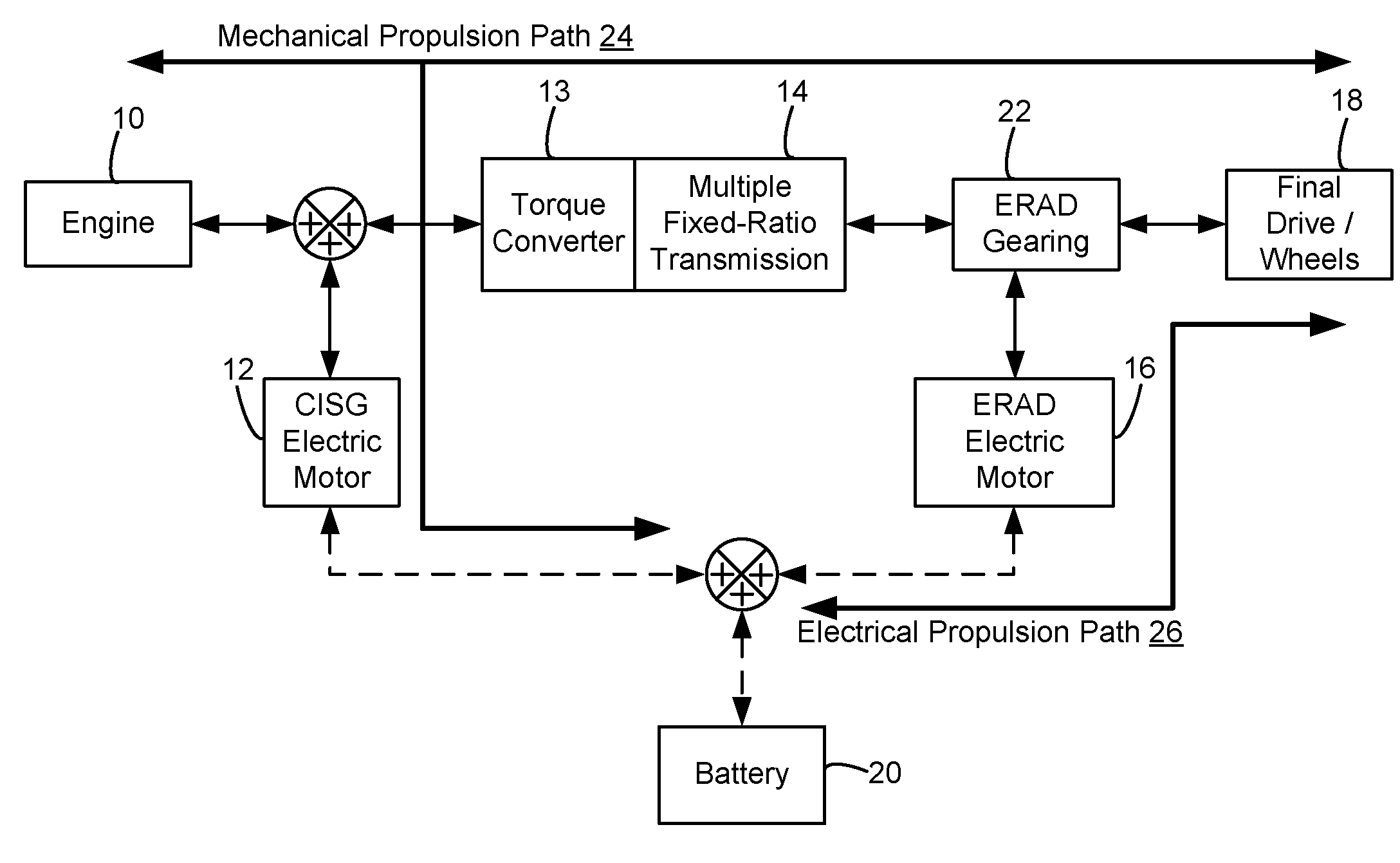
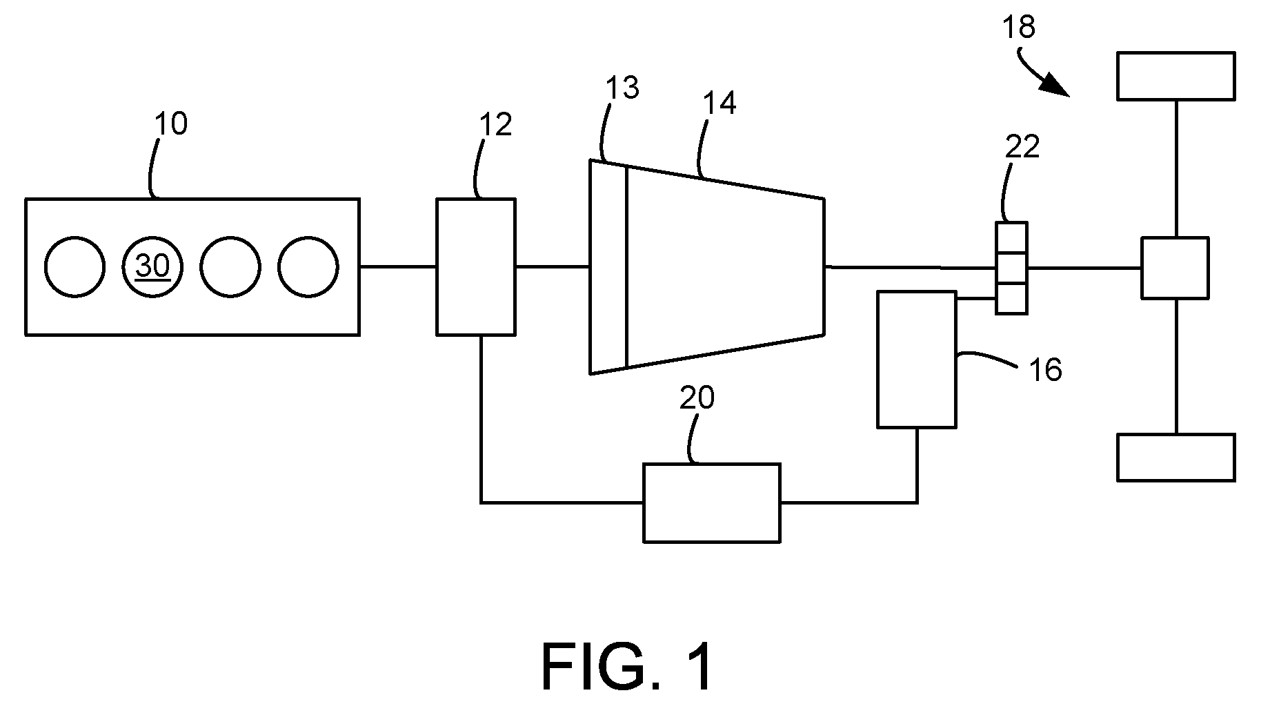
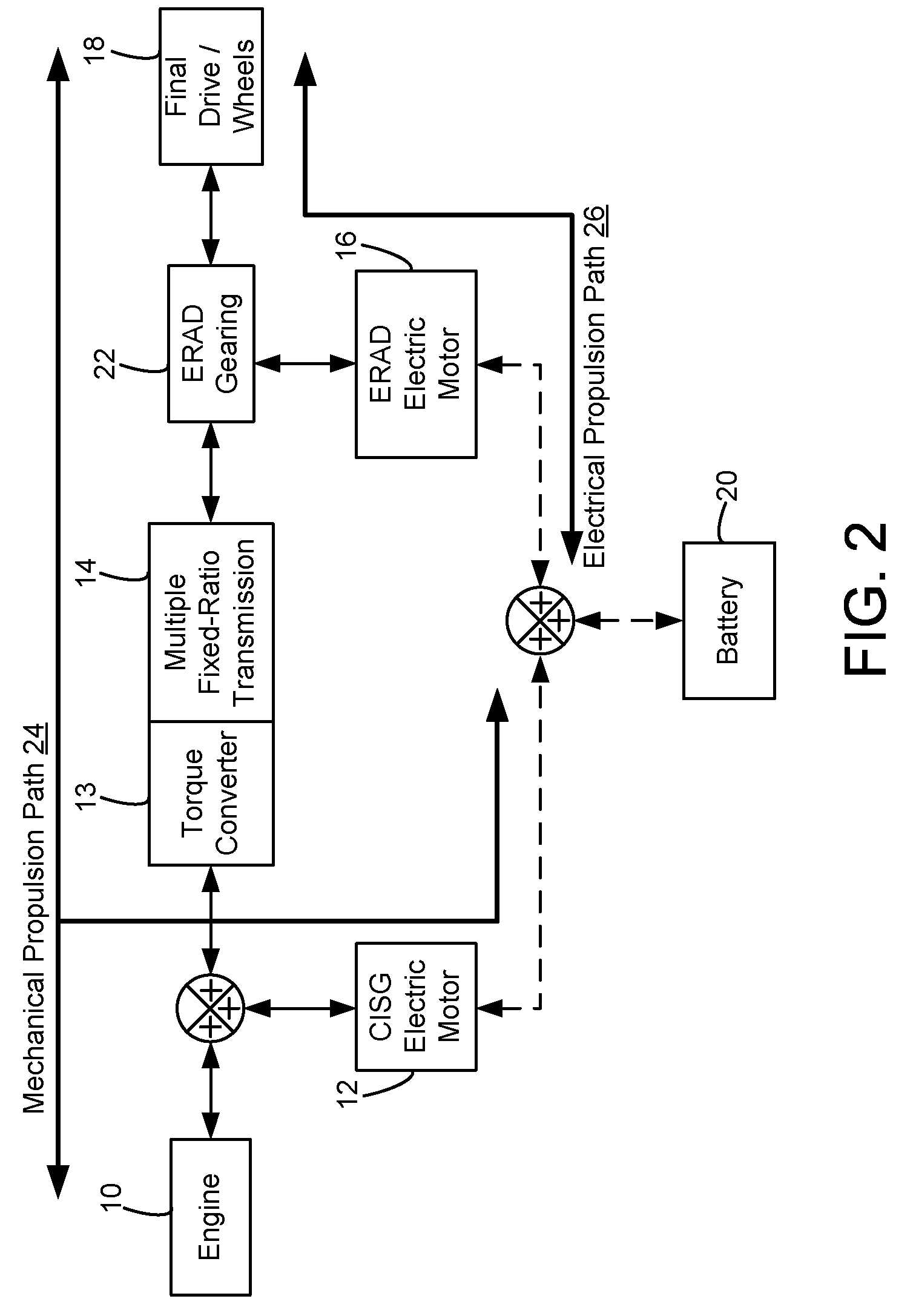
[0017]FIG. 1 illustrates an exemplary embodiment of a hybrid propulsion system for a vehicle. In particular, the exemplary powertrain configuration may be used with the disclosed powertrain control and shift scheduling approach. In this example, the hybrid propulsion system may include an Atkinson cycle internal combustion engine (ICE) 10 having one or more cylinders 30, a multiple fixed-ratio transmission 14, final drive / wheels 18 or other suitable device for delivering propulsive force to the ground surface, and two electric energy conversion devices 12 and 16. The first electric energy conversion device (CISG) 12 may be integrated at the output of engine 10 and further may be connected to the impeller of a torque converter 13 connected to transmission 14, thus providing starter / generator capabilities. The second electric energy conversion device (ERAD) 16 may be coupled to the output of transmission 14 through planetary gear set 22 which may be connected to a final / output drive, ...


PUM


Abstract

A method for improving hybrid vehicle is disclosed. In one embodiment, a torque differential across a transmission is controlled while torque is provided to the vehicle driveline / wheels to meet driver demand. The method may improve transmission shifting by allowing earlier shifts, for example.

Description

BACKGROUND AND SUMMARY[0001]In a hybrid powertrain, an electric energy conversion device, for example a motor / generator, may be used to absorb and / or supply torque to improve powertrain efficiency and fuel economy performance. In one example, a hybrid powertrain may include an internal combustion engine and an electric motor connected in series to a multiple fixed-ratio transmission. In this configuration, the electric motor produces torque output, which in turn, reduces the torque load of the internal combustion engine. Moreover, by operating the internal combustion engine at a reduced torque load, fuel economy performance of the hybrid powertrain may be improved while meeting driver demand. One approach that employs this configuration is described in U.S. Pat. No. 6,835,160.[0002]The inventors herein have recognized that the above approach may have some issues. In particular, in the above described configuration, the electric motor may be operated to improve fuel economy performan...

Claims


Application Information

Patent Timeline
Patent Type & Authority Patents(United States)
IPC IPC(8): B60W20/00
CPCB60K6/48B60K6/547B60W10/026B60W10/06B60W10/08B60W10/11B60W20/40B60W20/00B60W2510/0657Y02T10/6221Y02T10/6286Y10T477/26B60W2510/084Y02T10/62
Inventor SOLIMAN, IHABSILVERI, ANDREW
Owner FORD GLOBAL TECH LLC
Why Eureka
Try Eureka