Vibration isolator for container and the like, and method of using the same

a technology of vibration isolator and container, which is applied in the direction of transportation items, packaging, railway components, etc., can solve the problems of difficult use and handling, and achieve the effect of smooth operation

Inactive Publication Date: 2011-02-22
MUGEN
View PDF6 Cites 8 Cited by
  • Summary
  • Abstract
  • Description
  • Claims
  • Application Information

AI Technical Summary

Benefits of technology

[0004]The present invention has been made in view of such problems with which the prior art has encountered, and the purpose of the present invention is to provide a vibration isolator for container, and the like, and a method of using the same which are applicable to general containers, and allow the loaded articles to be protected against vibration at the time of transportation, and the like, with the cost being held to a minimum.
[0027]The container, or the like, is placed on the load carrying frame of the vibration isolator before being packed. The container, or the like, is equipped with latch receiving structures, and the container, or the like, is loaded such that the latches of the twist locks of the load carrying frame are fitted into the latch receiving structures of the container, or the like. By turning the latches of the twist locks in the load carrying frame of the vibration isolator, the latches can be prevented from being disconnected from the latch receiving structures, resulting in the container or the like, being firmly secured.
[0028]When the load carrying vehicle loaded with the container, or the like, is vibrated, the base frame of the vibration isolator is vibrated together. On the other hand, the load carrying frame of the vibration isolator is vibrated with the vibration being damped, because shock absorbing members are interposed between the base frame and the load carrying frame for absorbing the vibration. Thereby, no strong vibration will be transmitted directly to the articles loaded in the container, or the like, thus the vibration isolator having the shock absorbing members can provide protection.
[0029]In case that the shock absorbing members interposed between the base frame and the load carrying frame provide a plurality of pneumatic springs, the air therein serves as a cushion to sufficiently buffer the vibration. In addition, by adjusting the air pressure within the pneumatic springs, an appropriate shock absorbing action suited for the loaded articles is provided, which allows the function of the vibration isolator to be sufficiently exerted.
[0030]With some trailers, and the like, as load carrying vehicles, the compressed air created by means of the engine is utilized for controlling the brake. Likewise, with the vibration isolator, the compressed air pipe is connected to the air chuck to supply compressed air to the pneumatic springs as the shock absorbing members. The compressed air introduced through the air chuck is accumulated in the air reservoirs, and from the air reservoirs, the compressed air is supplied to the respective pneumatic springs. Thereby, the air pressure in the pneumatic springs, which are the shock absorbing members, can be maintained at an appropriate value or properly adjusted.
[0036]In addition, also with the vibration isolator being kept mounted on the load carrying vehicle, loading / unloading, and transport can be carried out. When the container, or the like, is loaded on the vibration isolator, the loaded articles, and the like, can be protected, the vibration during movement being buffered in the same way as described above. And, when the container, or the like, is loaded on the vibration isolator which is mounted on the load carrying vehicle, the shock absorbing members absorb the impact which is applied when the bottom face of the container, or the like, is butted against the load carrying frame of the vibration isolator, thus protecting the loaded articles, and the like.

Problems solved by technology

However, with such a prior art, the container is specialized, being required to be handled differently from the container which is generally used, thus presenting a difficulty in use and handling, and a problem that it is expensive, being a specialized item.

Method used


Image

  • Vibration isolator for container and the like, and method of using the same
  • Vibration isolator for container and the like, and method of using the same
  • Vibration isolator for container and the like, and method of using the same

Examples


Embodiment Construction

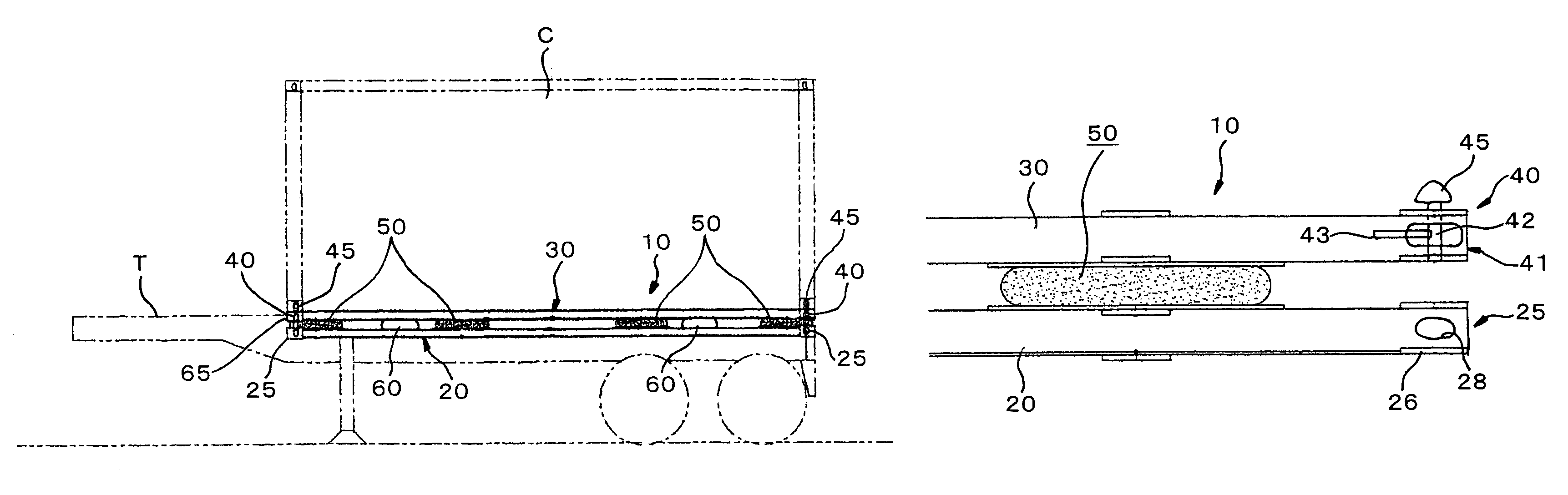
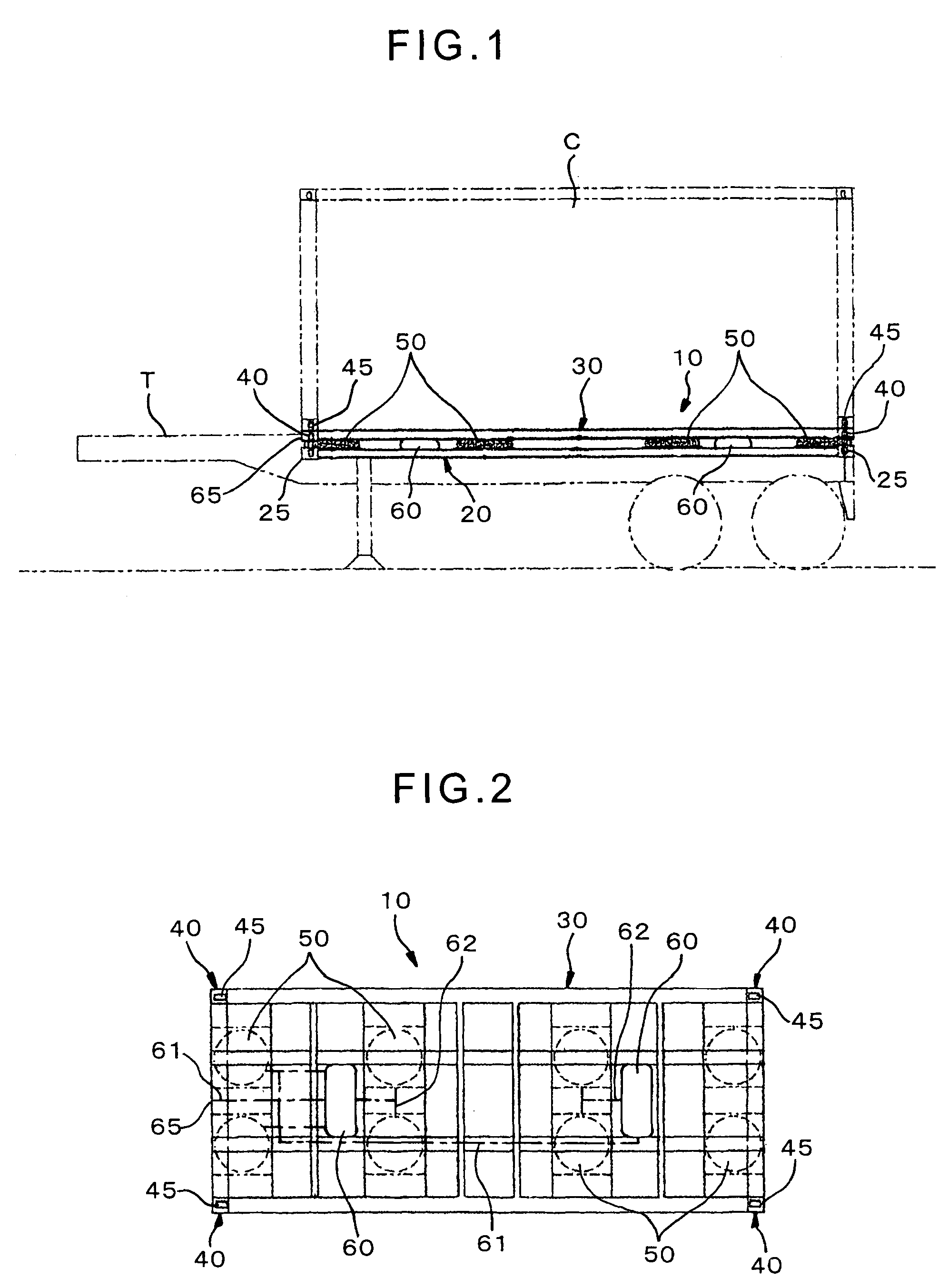
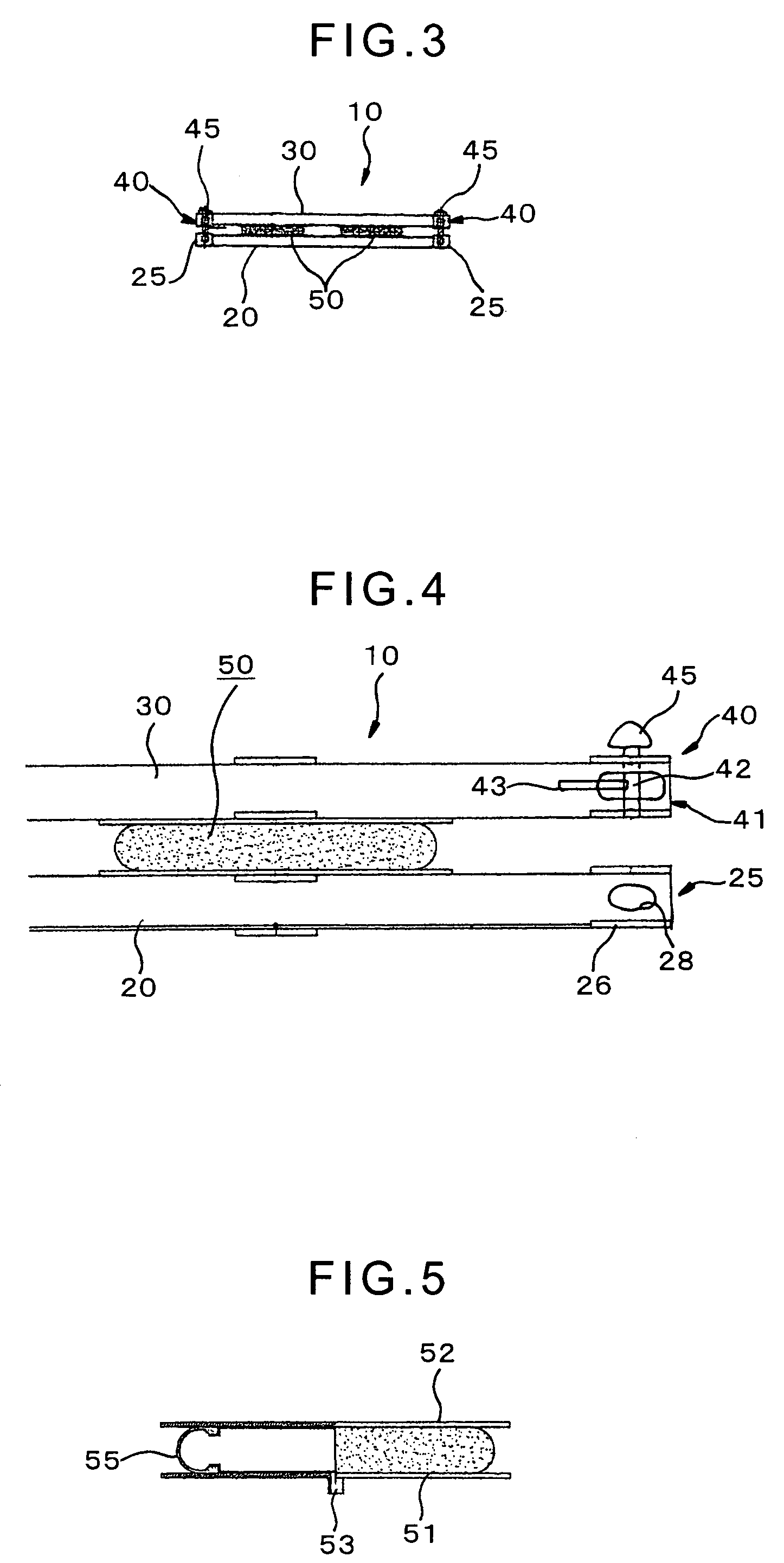
[0047]Hereinbelow, one exemplary embodiment of the present invention will be described with reference to the attached drawings. The respective figures show the one embodiment of the present invention. As shown in FIG. 1 to FIG. 3, a vibration isolator 10 provides vibration isolation for cargo protection, being interposed beneath a transport container C, a merchandise transport pallet, or the like, which is transported, being loaded on a load carrying vehicle, such as a trailer T, a vessel, a freight train, a cargo truck, or the like, and in the vibration isolator 10, shock absorbing members 50, 50, . . . are interposed between a base frame 20 and a load carrying frame 30.

[0048]The load carrying frame 30 is made up of steel members connected in the form of a lattice, and at the four corners thereof, a twist lock 40 is disposed. The base frame 20 is also made up of steel members connected in the form of a lattice, and at the four corners thereof, a latch receiving structure 25 for rec...


PUM


Abstract

A vibration isolator for container, and the like, and a method of using the same which are applicable to general containers, and allow the loaded articles to be protected against vibration at the time of transportation, and the like, with the cost being held to a minimum. It is a vibration isolator (10) for container (C), and the like, which provides vibration isolation for cargo protection, being interposed beneath a transport container (C), a merchandise transport pallet, or the like, wherein shock absorbing members (50) are interposed between a base frame (20) and a load carrying frame (30); and at least at the four corners of the base frame (20), a latch receiving structure (25) of a twist lock (40) is disposed, and in the corresponding place in the load carrying frame (30), a twist lock (40) is disposed.

Description

TECHNICAL FIELD[0001]The present invention relates to a vibration isolator for container, and the like, that provides vibration isolation for cargo protection, being interposed beneath a transport container, a merchandise transport pallet, or the like. The present invention also relates to a method of using the same.BACKGROUND ART[0002]Examples of the prior art include the art as disclosed in Japanese Patent Laid-Open Publication No. 2000-142212. Specifically, Japanese Patent Laid-Open Publication No. 2000-142212 discloses a container in which a container main body is disposed within an enclosure box, and between this enclosure box and the container main body, a shock absorbing structure is provided.DISCLOSURE OF THE INVENTION[0003]However, with such a prior art, the container is specialized, being required to be handled differently from the container which is generally used, thus presenting a difficulty in use and handling, and a problem that it is expensive, being a specialized it...

Claims


Application Information

Patent Timeline
Patent Type & Authority Patents(United States)
IPC IPC(8): B60P7/08
CPCB60P7/18B65D88/129B62D33/10B62D24/02B60P7/13B62D21/09B65D88/12
Inventor FUKUDA, AKIO
Owner MUGEN
Why Eureka
Try Eureka