Filling device with vertically arranged weighing device

a technology of vertical arrangement and filling device, which is applied in the direction of liquid handling, instruments, packaged goods, etc., can solve the problems of distorting weighing, complex design, and relatively sensitive known weighing device to vibration generated

Inactive Publication Date: 2014-10-28
KRONES AG
View PDF28 Cites 2 Cited by
  • Summary
  • Abstract
  • Description
  • Claims
  • Application Information

AI Technical Summary

Benefits of technology

[0009]The inventive arrangement of the weighing device at least in part vertically above the discharge opening of the filling valve allows a connection between the container and the weighing device that is substantially protected against vibrations in the gravity direction.
[0017]Preferably, the discharge opening is closable so that the area of the filling station contacted by the product can be cleaned in a hygienically impeccable manner and automatically, without there being a risk that the weighing device is damaged by wetness or possibly aggressive cleansing agents.

Problems solved by technology

However, due to this horizontally and radially extending arrangement the known weighing device is relatively sensitive to vibrations generated during the operation, which are induced by the rotation of the filler carrousel or by the forces acting for a short time on the containers, or the like.
These vibrations can distort the weighing result.
With respect to the filling valve outlet the lead-through aperture for the carrier member for the bottle is offset in a radially inward direction, is sealed with a bellows and has a very complex design.
If used for cold aseptic filling this area has to be cleaned and disinfected with aggressive media, which media could likewise affect the function.
Moreover, such internal attachments come along with constructive undercuts in which a reliable cleaning and disinfection is impossible or at least difficult.
In addition, maintenance and servicing of machine components inside the carrousel is complicated by the reduced accessibility.
The power transmission from the carrier member to the weighing device is very complex, however.

Method used


Image

  • Filling device with vertically arranged weighing device
  • Filling device with vertically arranged weighing device
  • Filling device with vertically arranged weighing device

Examples


Embodiment Construction

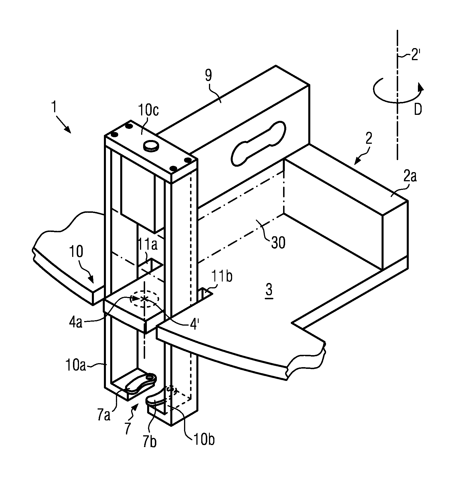
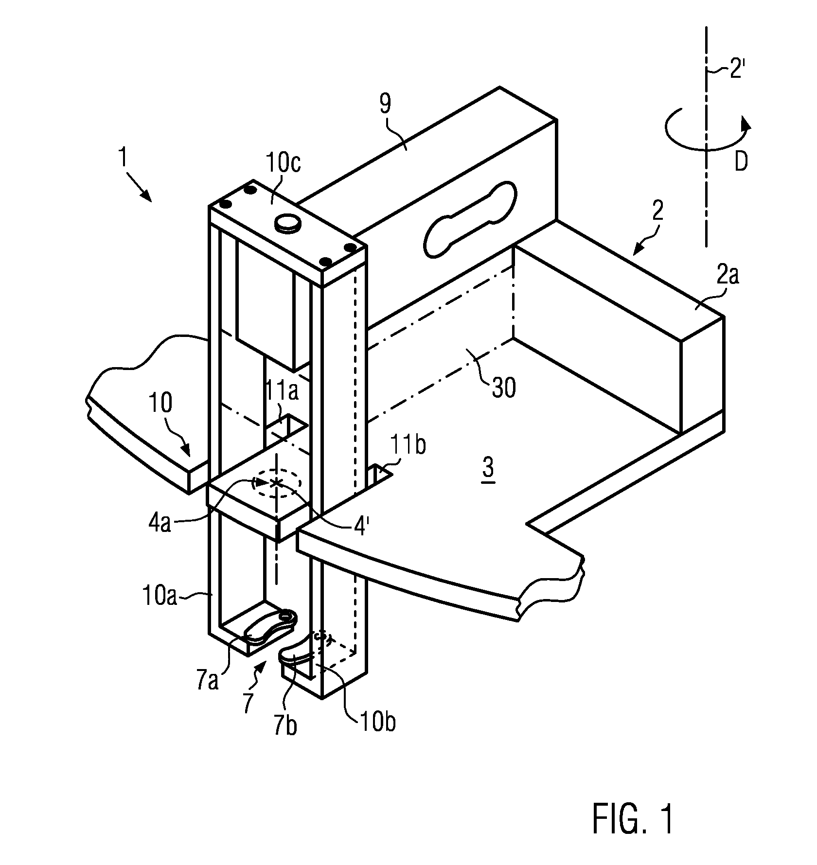
[0030]FIG. 1 shows a perspective view of a filling device 1 as part of a filling plant for the filling of beverages, which is, for example, a conventional filler carrousel. The filling plant includes a frame 2 which is driven to rotate about a substantially vertical axis of rotation 2′ in the direction of rotation D. In the embodiment shown merely a portion of an outer carrier part 2a, which belongs to the frame and extends about the axis of rotation 2′, can be seen, on which a plurality of substantially identical filling devices 1 are mounted in a manner distributed about the axis of rotation 2′.

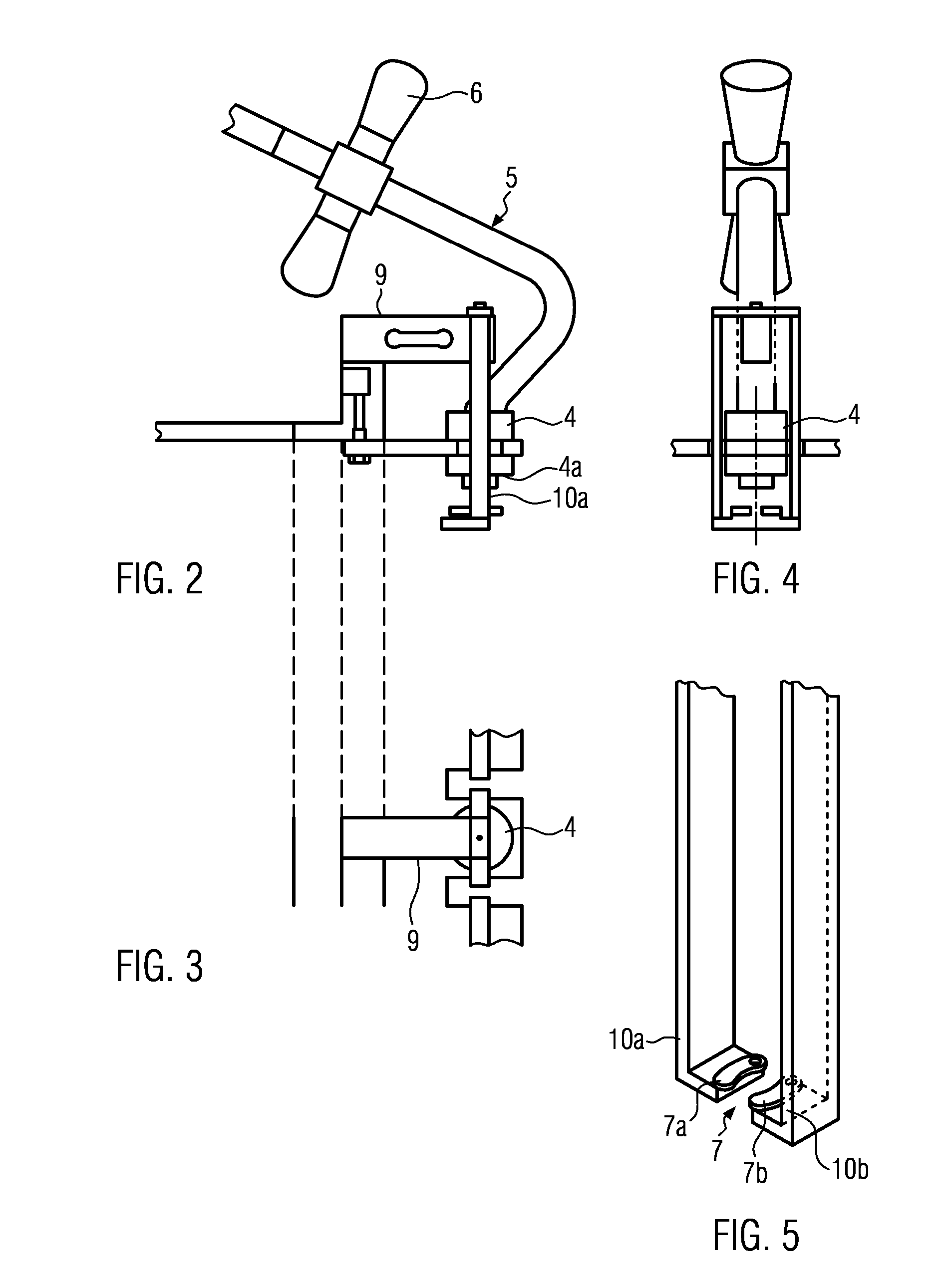
[0031]A carrier 3 is arranged on the carrier part 2a, which extends beyond the carrier part 2a in the radial direction relative to the axis of rotation 2′. This carrier 3 is designed as a valve receptacle for a filling valve 4. The filling valve 4 is of a common type and is connected by a supply line 5 and by shut-off members 6 to a source for the product to be filled in, especially a bever...


PUM

PropertyMeasurementUnit
outer circumferenceaaaaaaaaaa
weightaaaaaaaaaa
forcesaaaaaaaaaa

Abstract

A filling device for containers, especially for beverage bottles, having a filling valve with a discharge opening, a holder for the container in a suspended arrangement, and a weighing device. In order to obtain a robust weighing device and a more precise measurement at least one portion of the weighing device is arranged vertically above the discharge opening.

Description

CROSS-REFERENCE TO RELATED APPLICATION[0001]The present application claims the benefit of priority of German Application No. 102010041351.8, filed Sep. 24, 2010. The entire text of the priority application is incorporated herein by reference in its entirety.FIELD OF THE DISCLOSURE[0002]The disclosure relates to a filling device for containers, especially for beverage containers, of the type using a weighing device.BACKGROUND[0003]A filling device of this type is known from EP 1 025 424. The known filling device includes one of the usual filler carrousels, which run around a substantially perpendicular axis and are provided on their outer circumference with radially projecting holders for the containers. Typically, the holders are designed like tongs. The two jaws of the tongs are drawn towards each other under the load of a spring and define a recess that is adapted to the container, and by means of which the holder grips around the container for the filling thereof. Usually bottles...

Claims


Application Information

Patent Timeline
Patent Type & Authority Patents(United States)
IPC IPC(8): B67C3/20G01G13/00B65B3/28
CPCB67C3/202G01G15/00G01G17/06G01G11/08G01G21/28
Inventor SOBIECH, BERND
Owner KRONES AG
Why Eureka
Try Eureka