Engine device

a technology of engine and exhaust gas, which is applied in the direction of machines/engines, electric control of exhaust gas treatment, and jet propulsion mounting, etc., can solve the problems of reducing the temperature of the exhaust gas flowing into the exhaust gas purification device, the inability to stably install the inability to work effectively, so as to reduce the deposition of particulate matter in the exhaust gas purification device, the effect of increasing the temperatur

Active Publication Date: 2017-04-18
YANMAR POWER TECHNOLOGY CO LTD
View PDF20 Cites 5 Cited by
  • Summary
  • Abstract
  • Description
  • Claims
  • Application Information

AI Technical Summary

Benefits of technology

[0021]An exhaust gas temperature increasing mechanism for increasing temperature of the exhaust gas flowing to the exhaust gas purification device is disposed in a middle part of the exhaust pipe. Accordingly, an active increase of temperature of the exhaust gas by the exhaust gas temperature increasing mechanism can cause the exhaust gas purification device disposed away from the engine to effectively work, and hence deposition of particulate matter in the exhaust gas purification device can be suppressed.
[0022]An air cleaner for cleaning air taken into the engine and the exhaust pipe are disposed respectively on the left and right sides of the heat exchanger in the bonnet. Accordingly, it is possible to suppress an influence of heat discharged from the exhaust gas purification device to the air cleaner that is vulnerable to heat.

Problems solved by technology

As a result, even if a support structure for a silencer in the construction machine disclosed in Patent Document 2 is utilized as a support structure for an exhaust gas purification device, there is a problem that the exhaust gas purification device cannot be stably assembled.
In this case, if the exhaust gas purification device is disposed close to the engine in the engine mounting space, high frequency vibration of the engine may be transmitted to the exhaust gas purification device so that the exhaust gas purification device can be damaged.
For this reason, temperature of the exhaust gas flowing into the exhaust gas purification device is decreased so that particulate matter contained in the exhaust gas cannot be sufficiently burned and removed.
As a result, the particulate matter is deposited in the exhaust gas purification device, and consequently there is a problem that an output of the engine is decreased.

Method used


Image

  • Engine device
  • Engine device
  • Engine device

Examples


Embodiment Construction

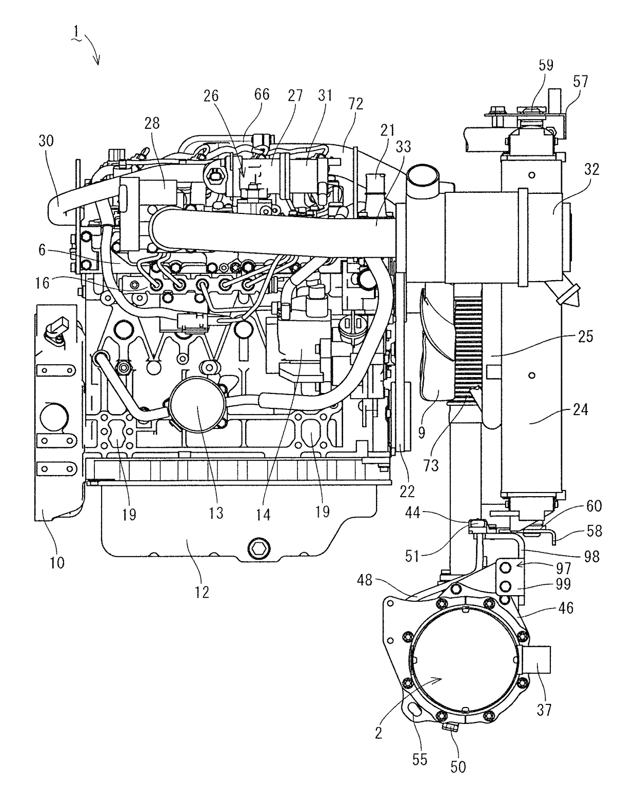
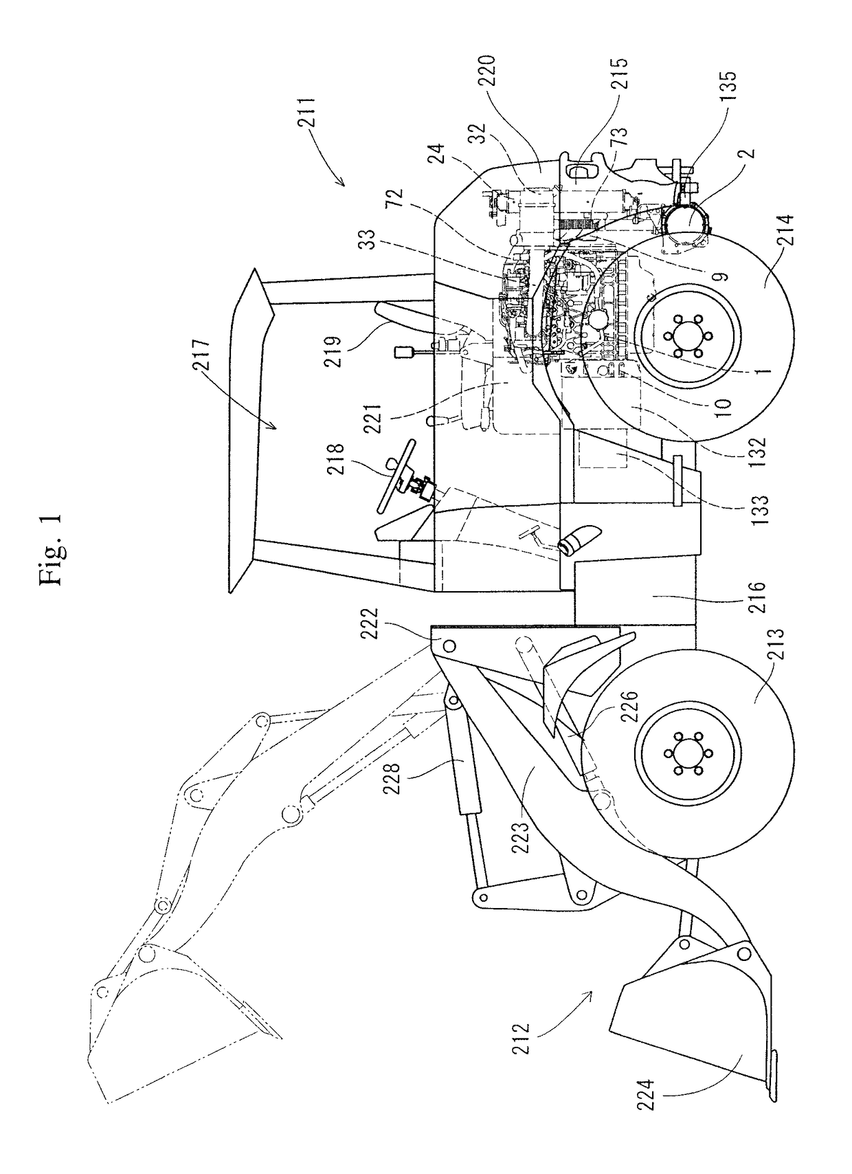
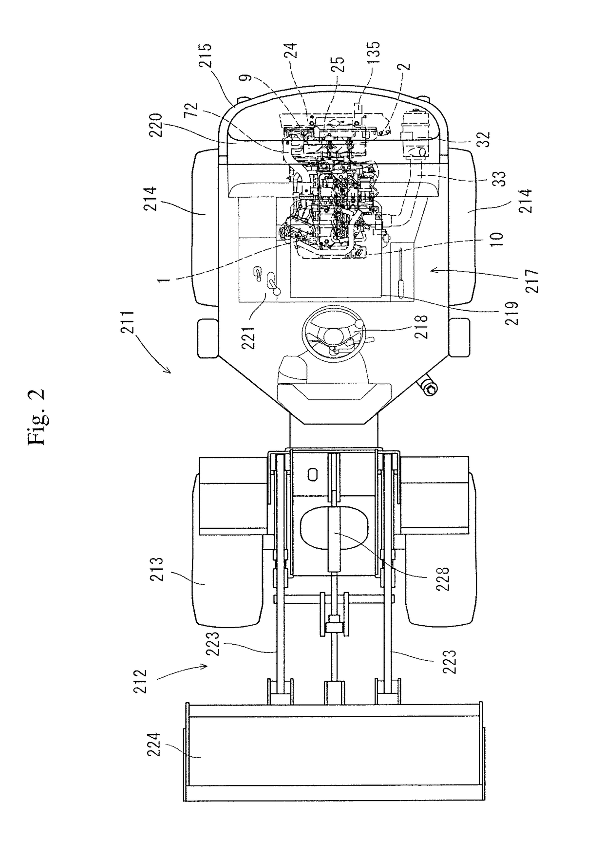
[0037]With reference to FIGS. 1 to 10, an embodiment of an engine device and a work machine equipped with the engine device according to the present invention is described on the basis of the drawings. Note that in the following description, a wheel loader equipped with a loader device as a work unit is exemplified as the work machine in this embodiment, and details of structure thereof will be described.

[0038]A wheel loader 211 shown in FIGS. 1, 2, and 10 includes a traveling machine body 216 equipped with left and right pairs of front wheels 213 and rear wheels 214. An operation portion 217 and an engine 1 are mounted in the traveling machine body 216. A loader device 212 as a work unit is attached to a front part of the traveling machine body 216 so that a loading work can be performed. In the operation portion 217, there are arranged an operator's seat 219 on which an operator sits, an steering wheel 218, operation means for operating an output of the engine 1 and the like, and ...


PUM


Abstract

An engine is disposed below an operator's seat in such a manner that a flywheel housing is located at the front of a traveling machine body. An exhaust gas purification device is disposed behind the engine and below a radiator. The engine is connected, on the left side thereof, to an air cleaner for taking in fresh air, and is connected, on the right side thereof, to an exhaust pipe which is connected to the air inlet side of the exhaust gas purification device.

Description

TECHNICAL FIELD[0001]The present invention relates to an engine device such as a diesel engine equipped with an exhaust gas purification device, and more specifically to an engine device which is mounted in a work machine such as a wheel loader, a backhoe, or a forklift truck.BACKGROUND OF THE INVENTION[0002]Conventionally, there is developed a technique of disposing an exhaust gas purification device (diesel particulate filter) in an exhaust path of a diesel engine so as to purify exhaust gas discharged from the engine by an oxidation catalyst, a soot filter, or the like of the exhaust gas purification device (see, for example, Patent Document 1). Further, in recent years, also in a field of work machines such as a construction machine or an agricultural machine, it is required to provide an exhaust gas purification device to a diesel engine used in the machine, as an environmental measure (see, for example, Patent Document 2).PRIOR ART DOCUMENTS[0003]Patent Document 1: JP-A-2000-1...

Claims


Application Information

Patent Timeline
Patent Type & Authority Patents(United States)
IPC IPC(8): B60K13/04E02F9/18E02F9/16B66F9/075F01N13/18B60K11/04F01N13/10F01N3/08E02F9/08B60K5/02F01N9/00
CPCF01N13/10B60K11/04B60K13/04B66F9/075B66F9/07595E02F9/0866E02F9/0891E02F9/16E02F9/18F01N3/08F01N13/1805B60K5/02B60Y2200/15B60Y2200/412B60Y2200/415F01N9/002F01N2470/18F01N2590/00
Inventor MITSUDA, MASATAKA
Owner YANMAR POWER TECHNOLOGY CO LTD
Why Eureka
Try Eureka