Drive system for aircraft landing gear

a technology for landing gear and drive system, which is applied in the direction of gear lubrication/cooling, gear vibration/noise damping, and toothed gearings, etc., can solve the problem of high transmission error and achieve the effect of improving efficiency and high transmission error

Active Publication Date: 2017-05-18
AIRBUS OPERATIONS LTD
View PDF0 Cites 2 Cited by
  • Summary
  • Abstract
  • Description
  • Claims
  • Application Information

AI Technical Summary

Benefits of technology

[0004]The use of a rotary damper protects the rest of the drive path from vibrations caused by transmission errors between the drive pinion and the driven gear.
[0005]Preferably one of the drive pinion and the driven gear comprises a roller gear having a series of rollers arranged to form a ring, each roller being rotatable about a roller axis (typically at a fixed distance from an axis of rotation of the drive pinion or driven gear, respectively), and the other of the drive pinion and the driven gear comprises a sprocket. The use of a rotary damper is particularly beneficial when

Problems solved by technology

The use of a rotary damper is particularly beneficial when used in combination with a rolle

Method used


Image

  • Drive system for aircraft landing gear
  • Drive system for aircraft landing gear
  • Drive system for aircraft landing gear

Examples


Embodiment Construction

)

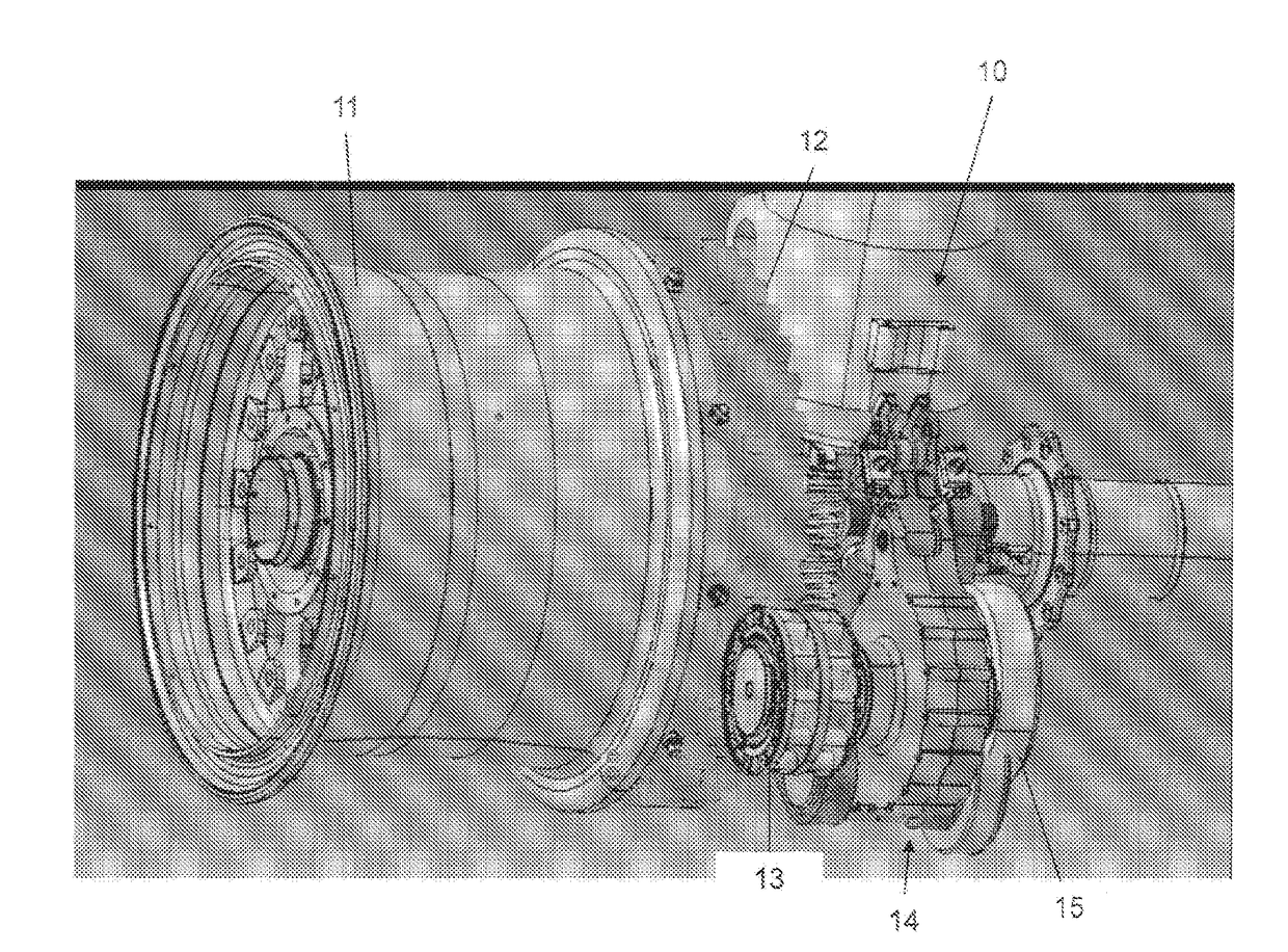
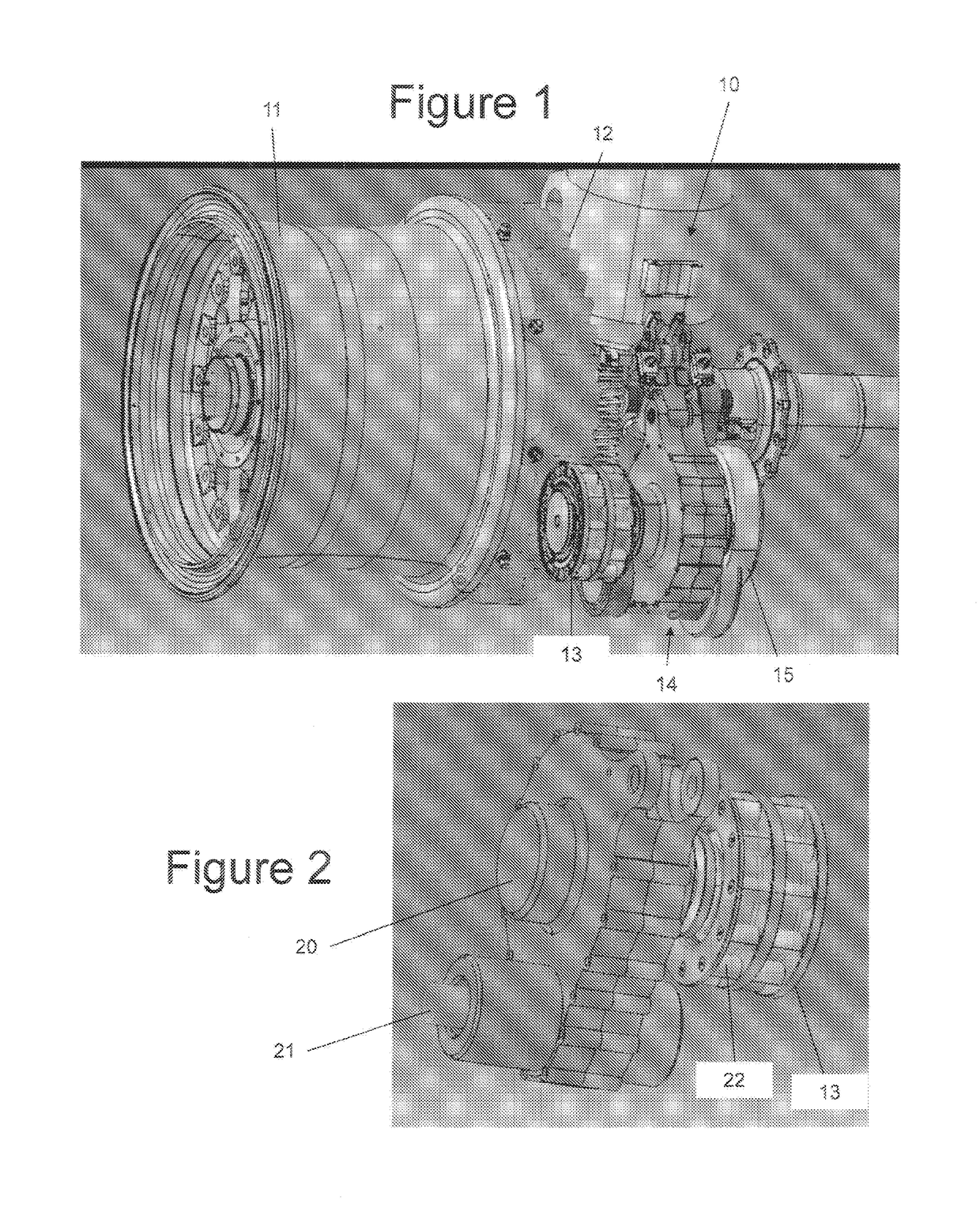
[0026]FIG. 1 shows an aircraft landing gear 10 comprising a wheel 11. A drive system for rotating the wheel 11 comprises a drive pinion 13; a motor 15 operable to rotate the drive pinion 13 via a drive path 14; and a driven gear 12 attached to the wheel so as to be capable of rotating the wheel. The drive system has a drive configuration shown in FIG. 1 in which the drive pinion meshes with the driven gear to permit the motor to drive the driven gear via the drive path.

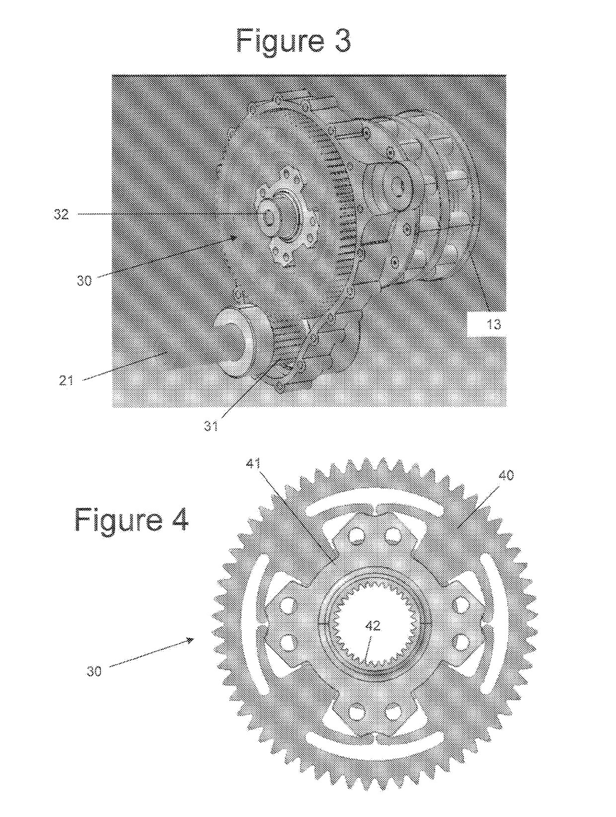
[0027]The drive pinion 13 comprises a roller gear having a series of rollers 22 arranged to form a ring, each roller being rotatable about a roller axis at a fixed distance from an axis of rotation. The driven gear 12 comprises a sprocket. In another embodiment, the rollers may be provided on the driven gear, and the pinion gear comprises a sprocket. A variety of suitable rollers gears are described in WO-A-2014 / 023939 and WO-A-2014 / 023941, the contents of which are incorporated herein by reference.

[0028]The drive pi...


PUM


Abstract

A drive system for rotating a wheel of an aircraft landing gear. The drive system has a drive pinion and a motor operable to rotate the drive pinion via a drive path. A rotary damper is provided in the drive path between the motor and the drive pinion. A driven gear is adapted to be attached to the wheel so as to be capable of rotating the wheel. The drive system has a drive configuration in which the drive pinion is capable of meshing with the driven gear to permit the motor to drive the driven gear via the drive path. One of the drive pinion and the driven gear comprises a roller gear having a series of rollers arranged to form a ring, each roller being rotatable about a roller axis, and the other of the drive pinion and the driven gear comprises a sprocket.

Description

FIELD OF THE INVENTION[0001]The present invention relates to a drive system for rotating a wheel of an aircraft landing gear.BACKGROUND OF THE INVENTION[0002]A drive system for rotating a wheel of an aircraft landing gear is shown in WO-A-2014 / 023939 and WO-A-2014 / 023941. The drive system comprises a drive pinion; a motor operable to rotate the drive pinion via a drive path; and a driven gear adapted to be attached to the wheel so as to be capable of rotating the wheel, wherein the drive system has a drive configuration in which the drive pinion is capable of meshing with the driven gear to permit the motor to drive the driven gear via the drive path.SUMMARY OF THE INVENTION[0003]A first aspect of the invention provides a drive system for rotating a wheel of an aircraft landing gear, the drive system comprising: a drive pinion; a motor operable to rotate the drive pinion via a drive path; a rotary damper in the drive path between the motor and the drive pinion: and a driven gear ada...

Claims


Application Information

Patent Timeline
IPC IPC(8): B64C25/40F16F15/16F16H57/04F16H1/24F16H57/00
CPCF16H57/042F16H57/0436F16H57/0417F16H57/0404F16F15/163F16H57/0006F16H2057/02043F16H2057/02034B64C25/405F16H1/24F16F15/162F16F15/073F16F15/161F16H55/10Y02T50/80
Inventor DIDEY, ARNAUDWILSON, FRASER
Owner AIRBUS OPERATIONS LTD
Why Eureka
Try Eureka