Glenoid augment and associated method

a technology of glenoid and associated methods, applied in the field of orthopaedics, can solve the problems of reducing the strength of the glenoid, and reducing so as to reduce the loosening of the implant, and eliminate the effect of shear for

Active Publication Date: 2011-02-22
DEPUY PROD INC
View PDF138 Cites 96 Cited by
  • Summary
  • Abstract
  • Description
  • Claims
  • Application Information

AI Technical Summary

Benefits of technology

[0023]The technical advantages of the present invention further include the ability of the prosthesis of the present invention to reduce loosening of the implant by matching the strain pattern of the glenoid to the implant or by providing an implant which experiences no shear force, and its normal force to the natural glenoid. For example and according to one aspect of the present invention, augmented glenoid assembly provided including a first component for attachment to the glenoid fossa. The first component defines a support surface and extends over a portion of the glenoid fossa. The first component has an assembly surface in alignment with the strain pattern to provide for no shear forces as does the support surface of the first component. Thus, the present invention provides for the reduction of loosening of the implant by providing a normal strain pattern and by eliminating the shear force.
[0024]Technical advantages of the present invention further include the ability of the glenoid assembly of the present invention to provide for modularity or for the combination of components to provide for a large variety of combinations with a smaller number of components. Such modularity provides for lower costs, reduced inventory, and greater offerings of combinations and better fit for patients. For example, according to another aspect of the present invention, an augmented glenoid assembly provides for cooperation with the glenoid fossa of the scapula. The implant assembly includes a first component for attachment to the scapula and a second component removably secured to the first component. Thus, the present invention provides for modularity or the combination of components to provide for greater flexibility and more offerings for the patient.
[0025]The technical advantages of the present invention also include the ability of the glenoid assembly of the present invention to include a glenoid bearing that may be used without a posterior defect. The present invention provides for use with a normal standard glenoid component. For example, according to another aspect of the present invention, an augmented glenoid assembly is provided for cooperation with the glenoid fossa of the scapula. The implant assembly includes a first component for attachment to the scapula and a second component removably secured to the first component. The first component extends over a portion of the glenoid fossa. The first component thus, may be used to accommodate the posterior defect. The augmented glenoid assembly also includes a second component that is positioned over substantially all the glenoid fossa. This second component may be identical to the glenoid component used for a natural glenoid without an extensive wear or posterior defect. Thus, the present invention provides for a glenoid bearing that may be used without a posterior defect.

Problems solved by technology

Such erosion of the scapula renders treatment difficult, if not impossible, with a conventional glenoid prosthesis.
The presence of a high shear load along the implant-to-bone interface tends to also cause loosening of the component 100 over a period of time.
Post-operative loosening is the largest cause of failures of implanted glenoid components.

Method used


Image

  • Glenoid augment and associated method
  • Glenoid augment and associated method
  • Glenoid augment and associated method

Examples


Embodiment Construction

[0077]Embodiments of the present invention and the advantages thereof are best understood by referring to the following descriptions and drawings, wherein like numerals are used for like and corresponding parts of the drawings.

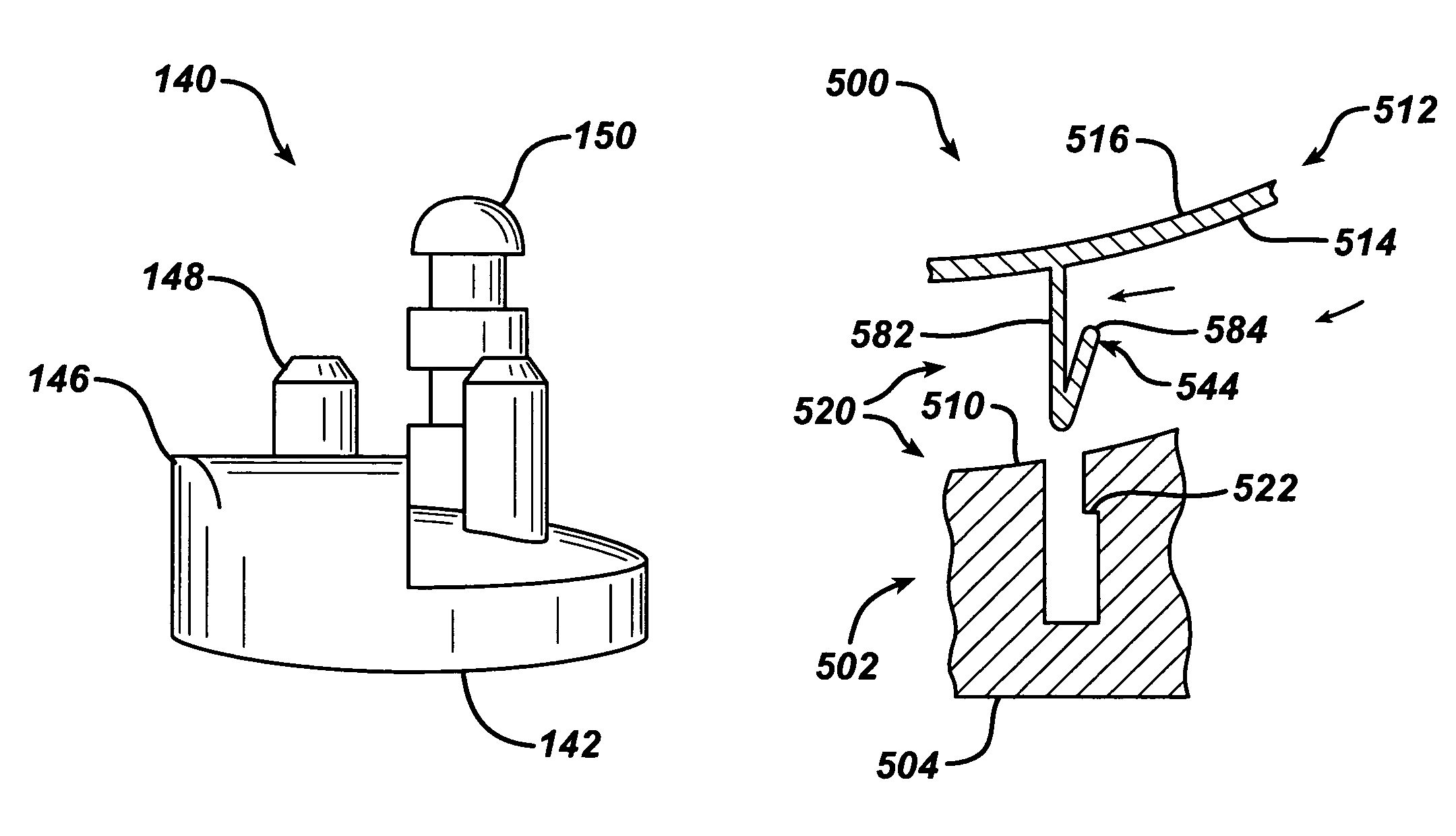
[0078]Referring now to FIG. 7-11, a stepped glenoid component 140 is shown in. The glenoid component 140 includes an articulating surface 142 as well as opposed mounting surfaces 144. The glenoid component 140 may include a posterior augment 146 as well as anchoring pegs 148 and a central peg 150.

[0079]According to the present invention and referring now to FIGS. 12 and 13, an augmented gleniod implant assembly 200 to shown for use in the glenoid fossa 115 of the scapula 116. The implant assembly 200 includes a first component 202 for attachment to the scapula 116. The first component 202 defines a support surface 204 for cooperation with the glenoid fossa 115. The first component 202 also includes a second surface 206 adapted to be adjacent, a buttress 208 fo...


PUM


Abstract

A augmented glenoid implant assembly for use in performing shoulder arthroplasty is provided. The augmented glenoid implant assembly is used for cooperation with the glenoid fossa of a scapula. The implant assembly includes a first component for attachment to the scapula. The first component defines a support surface for cooperation with the glenoid fossa, a second surface positioned adjacent a buttress formed in the glenoid fossa and an assembly surface. The implant assembly also includes a second component removably secured to the first component. The second component includes an assembly face of the second component. The assembly surface of the second component is in close approximation to the assembly surface of the first component. The second component further includes an articulating surface opposed to the assembly surface.

Description

TECHNICAL FIELD OF THE INVENTION[0001]The present invention relates generally to the field of orthopaedics, and more particularly, to an implant for use in arthroplasty.CROSS-REFERENCE TO RELATED APPLICATIONS[0002]Cross reference is made to the following applications: U.S. patent application Ser. No. 10 / 951,023 entitled “EXTENDED ARTICULATION PROSTHESIS ADAPTOR AND ASSOCIATED METHOD”, U.S. patent application Ser. No. 10 / 950,615 entitled “INSTRUMENT FOR PREPARING AN IMPLANT SUPPORT SURFACE AND ASSOCIATED METHOD”, U.S. patent application Ser. No. 10 / 951,021 entitled MODULAR GLENOID PROSTHESIS AND ASSOCIATED METHOD”, and U.S. patent application Ser. No. 10 / 951,022 entitled “GLENOID INSTRUMENTATION AND ASSOCIATED METHOD”, filed concurrently herewith which are incorporated herein by reference.BACKGROUND OF THE INVENTION[0003]During the lifetime of a patient, it may be necessary to perform a total shoulder replacement procedure on the patient as a result of, for example, disease or trauma...

Claims


Application Information

Patent Timeline
Patent Type & Authority Patents(United States)
IPC IPC(8): A61F2/40
CPCA61F2/30734A61F2/4081A61B17/86A61F2/30767A61F2002/30153A61F2002/30156A61F2002/30347A61F2002/30354A61F2002/30377A61F2002/30405A61F2002/30448A61F2002/30451A61F2002/30492A61F2002/30495A61F2002/305A61F2002/30604A61F2002/30616A61F2002/30736A61F2002/30822A61F2002/30878A61F2002/30881A61F2002/30884A61F2002/30897A61F2220/0025A61F2220/0033A61F2220/005A61F2220/0058A61F2230/0019A61F2230/0023A61F2310/00017A61F2310/00023A61F2310/00029A61F2310/00161A61F2310/00179A61F2310/00203A61F2310/00239A61F2002/30367
Inventor DEFFENBAUGH, DAREN LLOYD
Owner DEPUY PROD INC
Why Eureka
Try Eureka