Method and apparatus for countercurrent chromatography

a countercurrent chromatography and apparatus technology, applied in lighting and heating apparatus, separation processes, instruments, etc., can solve the problems of system failure to retain a satisfactory amount of stationary phase, loss of peak resolution, and affecting the efficiency of the system

Active Publication Date: 2011-02-22
UNITED STATES OF AMERICA
View PDF6 Cites 13 Cited by
  • Summary
  • Abstract
  • Description
  • Claims
  • Application Information

AI Technical Summary

Problems solved by technology

The maximum attainable retention level tends to fall sharply with the application of higher flow rates of the mobile phase, resulting in loss of peak resolution.
Consequently, the applicable flow rate has become one of the major limiting factors in countercurrent chromatography.
Although this system works reasonably well for some solvents, these systems often fail to retain a satisfactory amount of the stationary phase for highly viscous, low interfacial solvent systems such as polymer phase systems, which are useful for the separation of macromolecules and particulates.
In addition, the coiled tubing configuration is difficult to assemble, and connecting the ends of neighboring spiral tubing is rather difficult.

Method used


Image

  • Method and apparatus for countercurrent chromatography
  • Method and apparatus for countercurrent chromatography
  • Method and apparatus for countercurrent chromatography

Examples


example

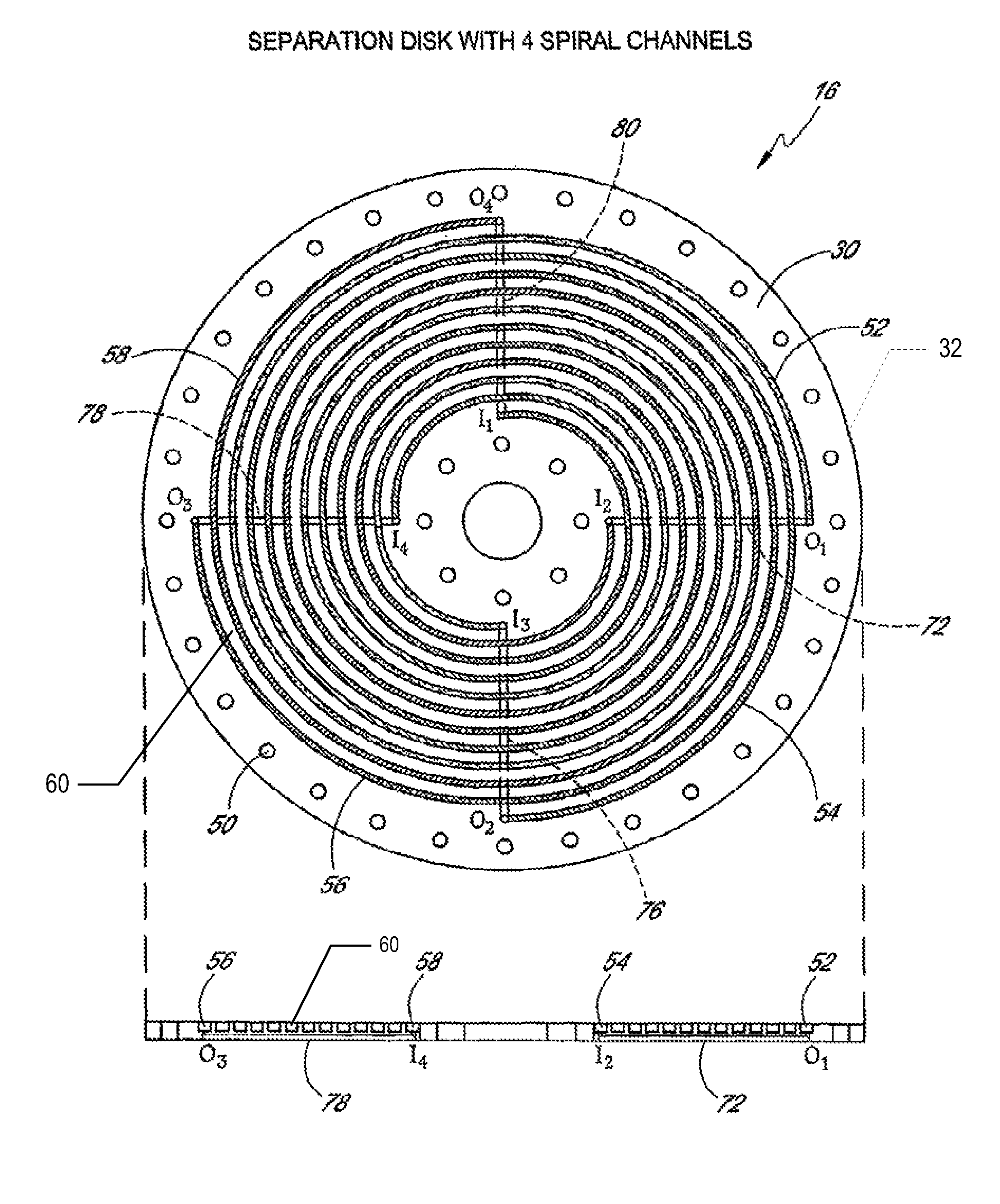
[0039]A suitable highly viscous, low interfacial two-phase solvent system is thoroughly equilibrated in a separatory funnel at room temperature and the two phases are separated before use. The sample solution is prepared by dissolving the sample in a proper volume (e.g. 1-5 ml) of the upper and / or lower phase of the solvent system. The spiral column assembly is first entirely filled with the stationary phase (upper or lower phase), followed by sample injection through the sample port The apparatus is rotated at 800 rpm while the mobile phase is eluted through the column at a desired flow rate. The separation may be repeated by changing the direction of the revolution and / or elution mode (i.e., head to tail and tail to head), although it is expected that the best result would be obtained by eluting the lower phase from the internal terminal toward the external terminal of the spiral channel at tail to head elution mode or the upper phase from the opposite direction in the head to tai...


PUM

PropertyMeasurementUnit
thicknessaaaaaaaaaa
thicknessaaaaaaaaaa
thicknessaaaaaaaaaa

Abstract

A countercurrent chromatography apparatus includes a plurality of plates, at least one plate (16) having first and second interleaved spiral flow channels (52, 54, 56, 58) therein. Each spiral flow channels (52, 54, 56, 58) has a first end (I1, I2, I3, I4) near the central axis and a second ends (O1, O2, O3, O4) near the periphery. The outlet of the first channel (O1) is connected to the inlet of the second channel (I2) by a connecting channel (72). Septa may be provided between the plates to connect the spiral channels of one plate to the spiral channels of the next plate.

Description

BACKGROUND OF THE INVENTION[0001]1. Field of the Invention[0002]The invention relates to countercurrent chromatography systems, and more particularly to an improved column design for use in countercurrent chromatography.[0003]2. Description of the Related Art[0004]Chromatography is a separation process that is achieved by distributing the substances to be separated between a mobile phase and a stationary phase. Those substances distributed preferentially in the moving phase pass through the chromatographic system faster than those that are distributed preferentially in the stationary phase. As a consequence, the substances are eluted from the column in inverse order of their distribution coefficients with respect to the stationary phase.[0005]Chromatography is widely used for the separation, identification, and determination of the chemical components in complex mixture. Chromatographic separation can be utilized to separate gases, volatile substances, nonvolatile material, and poly...

Claims


Application Information

Patent Timeline
Patent Type & Authority Patents(United States)
IPC IPC(8): B01D15/08B07B7/00B01D15/18G01N30/42
CPCB01D15/1807B01D15/1892G01N30/42
Inventor ITO, YOICHIRO
Owner UNITED STATES OF AMERICA
Why Eureka
Try Eureka