Triangular rollable and collapsible boom

a boom and triangular technology, applied in the field of booms, can solve the problems of limiting the performance of most applications, bending stiffness is the limiting measure of bending stiffness, and the cross-section inertia is large, so as to reduce the torsional stiffness of the boom, and the effect of thicker flange materials

Active Publication Date: 2011-03-01
THE GOVERNMENT OF THE UNITED STATES AS REPSESENTED BY THE SEC OF THE AIR FORCE
View PDF13 Cites 60 Cited by
  • Summary
  • Abstract
  • Description
  • Claims
  • Application Information

AI Technical Summary

Benefits of technology

[0005]The Triangular Reliable and Collapsible (TRAC) boom is a boom structure composed of a resilient material that is elastically deployable from a flattened configuration stowed around a circular hub to a deployed configuration having an open substantially triangular cross-section formed from two curved flanges attached at their upper portions. This results in a large cross-section inertia to packaged height ratio compared to Storable Tubular Extendable Member (STEM) and Collapsible Tubular Mast (CTM) architectures. While this design somewhat decreases the torsional stiffness of the boom, sufficient torsional stiffness remains such that bending stiffness is the limiting measure of performance for most applications. In addition, the strain required to flatten the flanges of a TRAC boom are smaller than previous booms allowing for thicker flange materials to be used. The combination of thicker materials and a larger deployed cross section results in a boom that has much greater bending stiffness than alternate technologies. Predicted performance of the TRAC boom indicate 10 times greater bending stiffness than a CTM boom with the same packaged height and material and 34 times greater bending stiffness than a STEM boom.

Problems solved by technology

This results in a large cross-section inertia to packaged height ratio compared to Storable Tubular Extendable Member (STEM) and Collapsible Tubular Mast (CTM) architectures.
While this design somewhat decreases the torsional stiffness of the boom, sufficient torsional stiffness remains such that bending stiffness is the limiting measure of performance for most applications.

Method used


Image

  • Triangular rollable and collapsible boom
  • Triangular rollable and collapsible boom
  • Triangular rollable and collapsible boom

Examples


Embodiment Construction

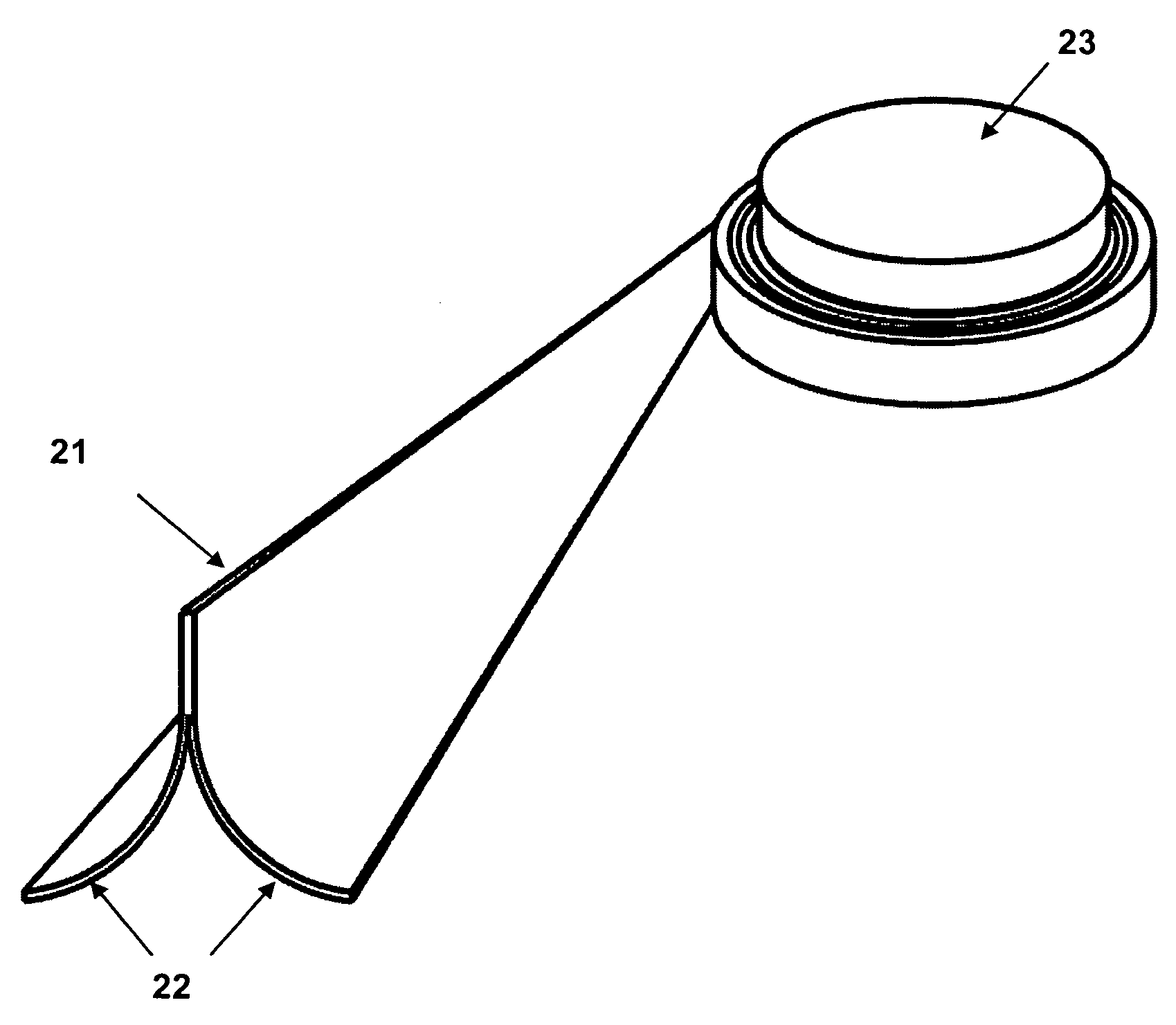
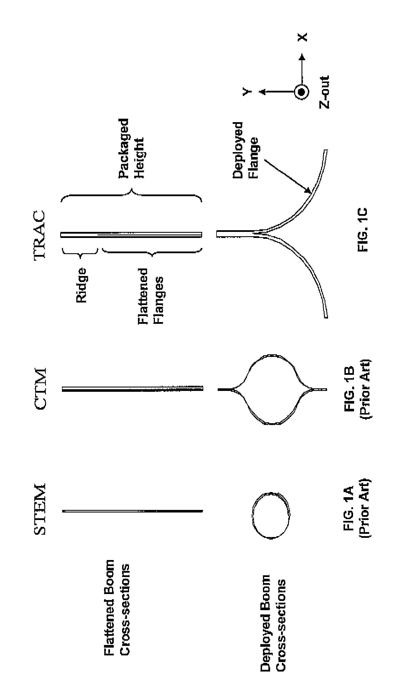
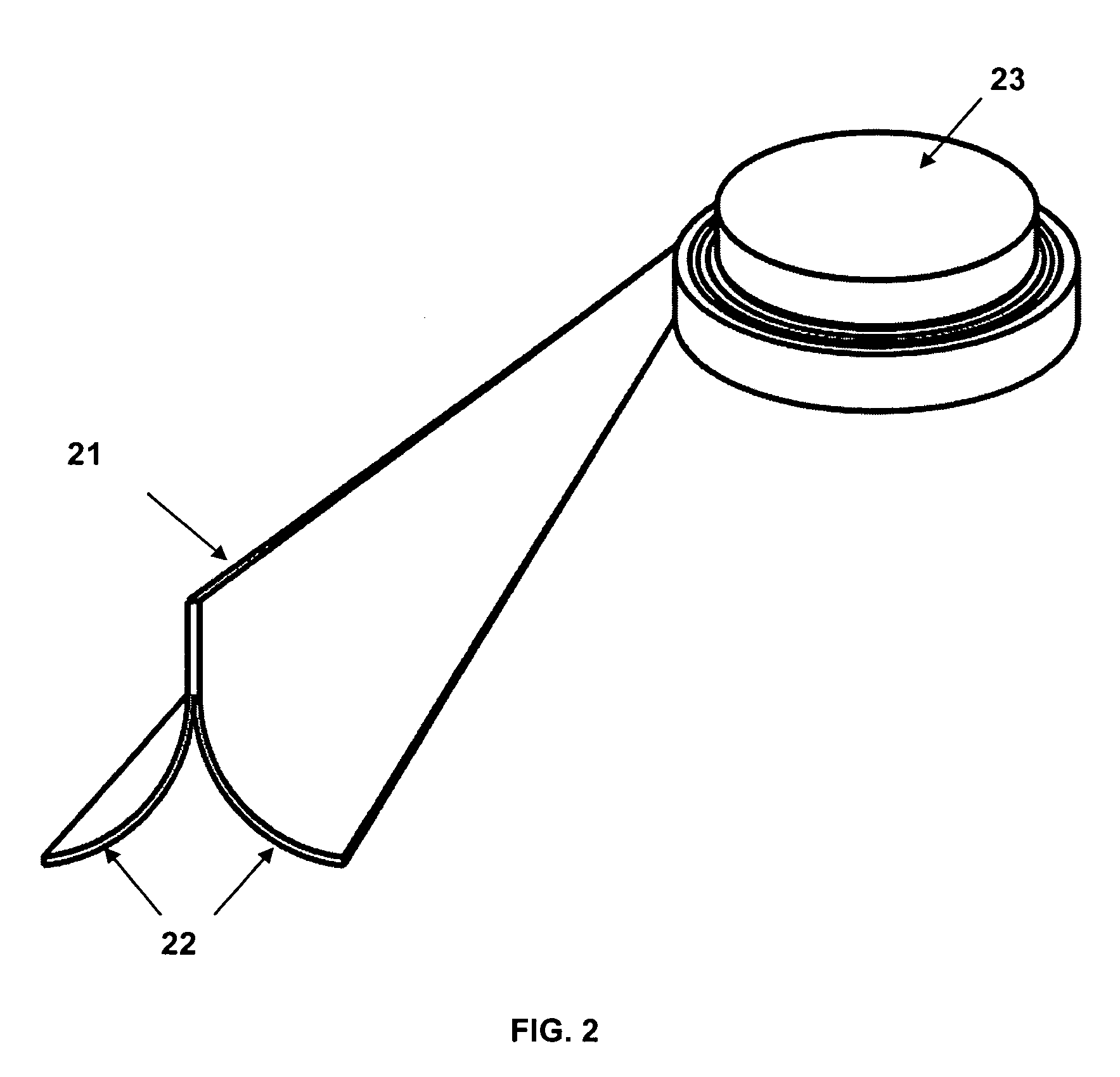
[0016]As seen in the cross-sectional view of FIG. 1C and in FIG. 2, the Triangular Rollable and Collapsible (TRAC) boom consists of a ridge where the upper portion of two curved flanges are attached to one another forming an open substantially triangular cross-section in its deployed configuration. The boom 21 is designed such that in the stowed position its two curved flanges 22 are pinched together allowing it to furl around a circular hub 23 as seen in FIG. 2. The key to achieving the rolling capability is that the flanges are elastically stable in the rolled configuration, e.g., the interior boom flange that is in compression does not bifurcate in the stowed configuration where the curved flanges are forced into a flat configuration. The resilient material employed, the radius of curvature of the flange arc, and the thickness of the flanges determine the strain required to flatten the cross section. A smaller radius of curvature of the flange arcs leads to a stiffer boom, but if...


PUM


Abstract

An elastic space-deployable boom of carbon fiber reinforced plastic or other resilient material having an open substantially triangular cross-section when deployed and stowed with a flattened cross-section about a circular hub.

Description

STATEMENT OF GOVERNMENT INTEREST[0001]The conditions under which this invention was made are such as to entitle the Government of the United States under paragraph I(a) of Executive Order 10096, as represented by the Secretary of the Air Force, to the entire right, title and interest therein, including foreign rights.BACKGROUND OF THE INVENTION[0002]The present invention relates generally to spacecraft deployable structures and more particularly to a boom architecture that can be flattened and furled and has a large cross-section inertia.[0003]The subject booms have a deployed configuration where they are used as beam-like structural elements to carry bending and column loads. Boom bending stiffness characterizes this configuration and increases with increasing structural depth (cross section diameter), material thickness and material stiffness. These booms also have a furled (packaged) configuration characterized by roll diameter and height. Prior booms related to the current inven...

Claims


Application Information

Patent Timeline
Patent Type & Authority Patents(United States)
IPC IPC(8): E04H12/18
CPCB64G1/222E04C3/005E04C3/28
Inventor MURPHEY, THOMAS W.BANIK, JEREMY
Owner THE GOVERNMENT OF THE UNITED STATES AS REPSESENTED BY THE SEC OF THE AIR FORCE
Why Eureka
Try Eureka