Separator spline and cables using same

a technology of separater spline and cable, applied in the direction of cables with twisted pairs/quads, etc., can solve the problems of increasing network speed, increasing the workload of graphic and interactive web-based systems, and increasing the demands of network transfer speed, so as to achieve the effect of less material and easy construction and us

Active Publication Date: 2011-03-01
BELDEN INC
View PDF149 Cites 19 Cited by
  • Summary
  • Abstract
  • Description
  • Claims
  • Application Information

AI Technical Summary

Benefits of technology

For these and other reasons there are described herein multi-part cables, methods of constructing multi-part cables, and other related systems, networks, and structures for forming cables, such as but not limited to, category cables (e.g., CAT6 cable) or other data cables, which include a separator spline or filler. This will generally be in the form of a T-shaped filler for a standard cable configuration including four twisted pair component cables. The T-shaped filler provides for a spline which provides physical separation where it is most needed in a four pair cable, while eliminating a leg from a more traditional X-shaped spline for the least needed material separation portion to provide for material savings in the spline's construction and generally provide a cable which can utilize less material, may be easier to construct and use, and still meets desired data transmission standards.

Problems solved by technology

Streaming media, more intense graphics, and interactive web-based systems are increasingly demanding of speed in network transfer.
That is, the component cables “talk” in a manner that is undesirable by sharing signals or allowing signals to finish propagating in a component other than the one in which they began propagating.
Cross-talk can serve to corrupt data, and in high-speed networks, can cause the network to slow.
The problem is particularly acute in CAT6 cables where, in its optimal format, all four twisted pairs (component cables) are utilized for data transmission.
Higher standards are generally too rigorous, however, for this limited prevention and it is desirable to further insulate the twisted pairs from each other.
In most cases, however, the separation cannot be maintained within the resultant cable without additional structure and a physical barrier is necessary.
While these fillers have helped improve cross-talk characteristics, they are not necessarily ideal in all situations.
Cross-shaped fillers keep the twisted pairs separated by some of the filler material, even when compressed, but often do so at the expense of over-correction.
However, this physical barrier can be unnecessary with regards to certain of the pairs for the prevention of certain levels of cross talk.
The inclusion of unnecessary material to form the cross-shaped spline for cables designed to meet these standards therefore can make the cross-shaped construction both more expensive and more difficult to manufacture without it being really necessary.
Further, because of the excess material within the cable, the resulting cable can have an increased fire risk and is generally more rigid and physically larger in construction than may be necessary.
These characteristics can make the cable less useful and harder to work with.

Method used


Image

  • Separator spline and cables using same
  • Separator spline and cables using same
  • Separator spline and cables using same

Examples


Embodiment Construction

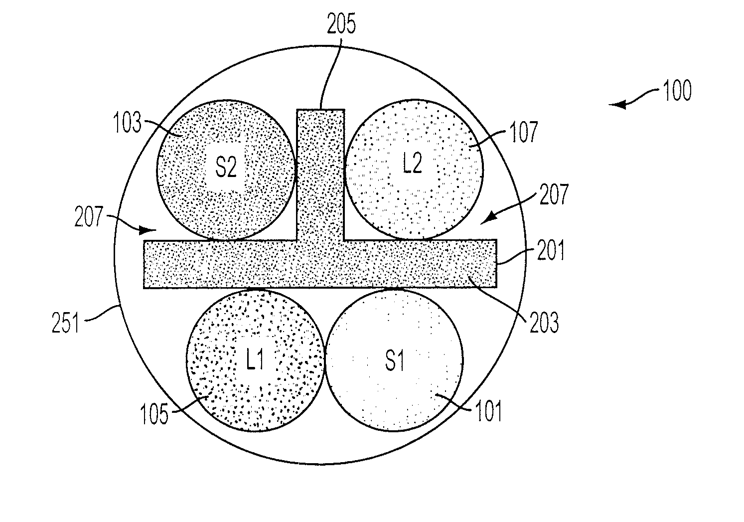
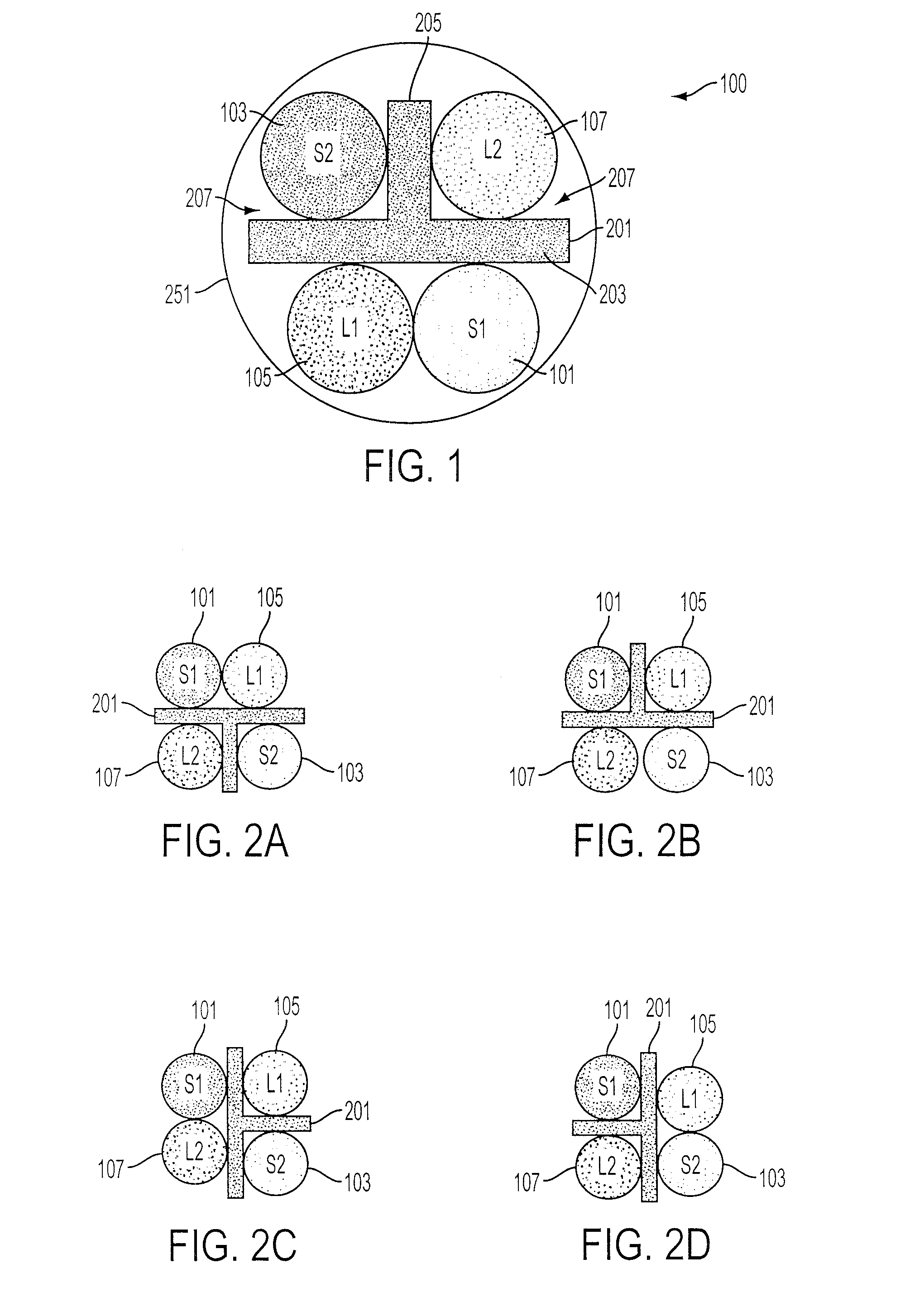
FIG. 1 shows a cross-sectional representative view of an embodiment of a cable (100) including a T-shaped spline (201). This view is taken along the plane of the latitudinal dimension of the cable showing a cross section across the longitudinal dimension which extends into and out of the sheet. The cable comprises four component cables (101), (103), (105), and (107). In this conceptual cross-section, these component cables (101), (103), (105), and (107) are indicated by circles to show the general area taken up by each cable as is conventional in illustrations in the industry. FIG. 4 provides for a perspective view of an embodiment of a cable showing a more realistic example of each twisted pairs' layout. These component cables (101), (103), (105), and (107) will generally comprise two individually insulated conductors, which are wrapped around each other in a generally helical construction to provide for a twisted-pair data cable.

The four component cables (101), (103), (105) and (1...


PUM

PropertyMeasurementUnit
lay lengthaaaaaaaaaa
degree anglesaaaaaaaaaa

Abstract

A cable, specifically a data cable, which utilizes a T-shaped spline to separate four internal data cables. This cable is a specific form of a more general cable which utilizes a central spline which is designed to separate all but one pair of component cables to provide for material savings in cable construction which still sufficiently reducing cross-talk to meet data cable design specifications.

Description

BACKGROUND OF THE INVENTION1. Field of the InventionThis disclosure relates to the field of electronic cables. In particular, to high speed data cables (category or premise cables) and other cables that utilize fillers or splines.2. Description of Related ArtElectronic devices, and computers in particular, are starting to become ever more connected. Just 20 years ago the idea of a computer network where machines talked with each other was simply a dream. Streaming media, more intense graphics, and interactive web-based systems are increasingly demanding of speed in network transfer. Today, people from around the world are connected to computer networks which are both local (such as LANs) and worldwide in scope (such as the Internet).As computers have become increasingly interconnected, there has arisen a more pronounced need for the cables and connectors used to connect them to be able to transfer more information in the same amount of time. While wireless networks have attracted a ...

Claims


Application Information

Patent Timeline
Patent Type & Authority Patents(United States)
IPC IPC(8): H01B11/02
CPCH01B11/06
Inventor GAREIS, GALEN M.
Owner BELDEN INC
Why Eureka
Try Eureka