Coaxial transmission line microstructures and methods of formation thereof

a technology of transmission line microstructure and coaxial transmission line, which is applied in the direction of waveguides, antennas, insulation conductors/cables, etc., can solve the problems of inability to simple join the two structures, inability to achieve simple joining of the two structures, and inability to achieve propagating wave reflection to a degree that is not acceptable for most applications

Active Publication Date: 2011-03-01
CUBIC CORPORATION
View PDF12 Cites 116 Cited by
  • Summary
  • Abstract
  • Description
  • Claims
  • Application Information

AI Technical Summary

Benefits of technology

[0012]In accordance with a further aspect of the invention, provided are methods of forming a coaxial transmission line microstructure. The methods include: disposing a plurality of layers over a substrate, wherein the layers comprise one or more of dielectric, conductive and sacrificial materials; and forming from the layers a center conductor, an outer conductor disposed around the center conductor, a non-solid volume between the center conductor and the outer conductor and a transition structure for transitioning between the coaxial transmission line and an electric connector.

Problems solved by technology

In this regard, the process of connecting an external element to a coaxial transmission line microstructure is fraught with problems.
Given the rather large difference in size between the microstructure and connector, a simple joining of the two structures is not possible.
Such a junction typically produces attenuation, radiation, and reflection of the propagating waves to a degree that is not acceptable for most applications.
Adding to the difficulty of microstructure connectivity is the relatively delicate nature of the microstructures when considering the forces typically exerted on such connectors.
Although periodic dielectric members are provided in the described microstructures to support the center conductor along its length, the microstructures are still susceptible to breakage and failure caused by excessive mechanical stresses.
Still further, when transitioning between the coaxial transmission line and another element through which an electric and / or electromagnetic signal is communicated, signal loss due to attenuation and return reflection can be problematic.
In addition to loss of signal, return reflection can cause failure of circuits and / or failure of circuits to perform properly.

Method used


Image

  • Coaxial transmission line microstructures and methods of formation thereof
  • Coaxial transmission line microstructures and methods of formation thereof
  • Coaxial transmission line microstructures and methods of formation thereof

Examples


Embodiment Construction

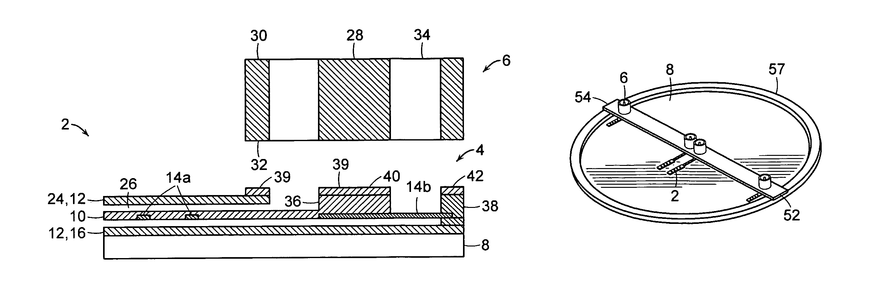
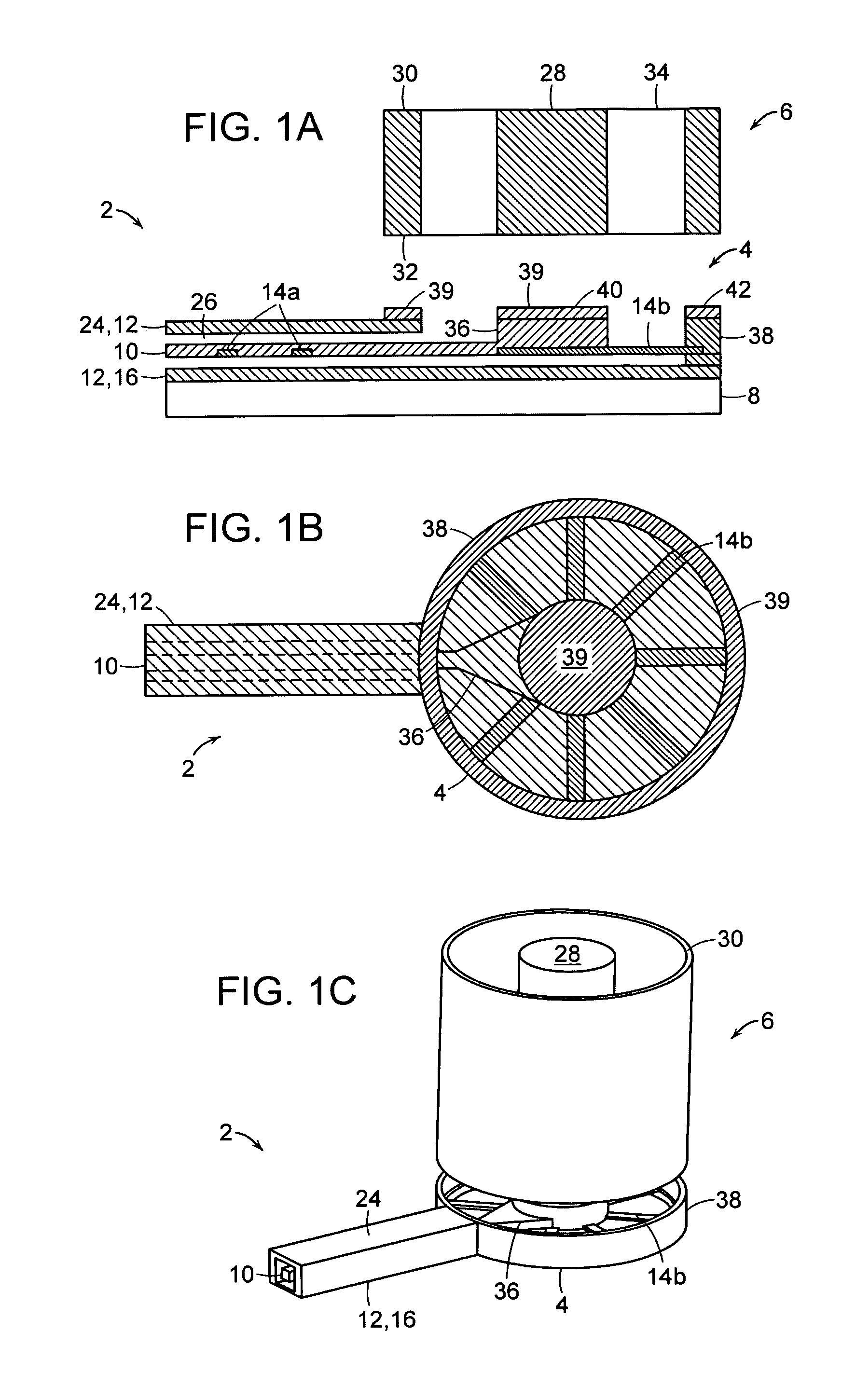
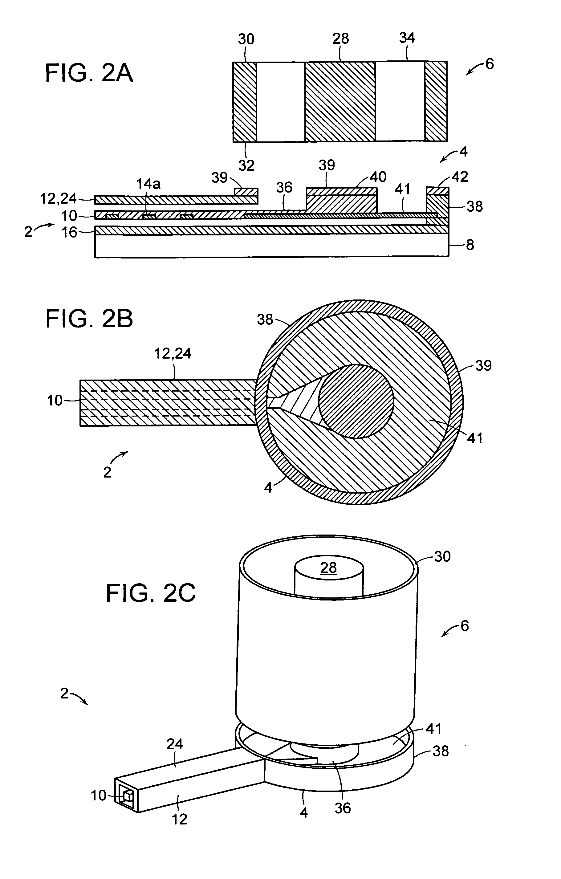
[0022]The exemplary processes to be described involve a sequential build to create three-dimensional microstructures. The term “microstructure” refers to structures formed by microfabrication processes, typically on a wafer or grid-level. In the sequential build processes of the invention, a microstructure is formed by sequentially layering and processing various materials and in a predetermined manner. When implemented, for example, with film formation, lithographic patterning, deposition, etching and other optional processes such as planarization techniques, a flexible method to form a variety of three-dimensional microstructures is provided.

[0023]The sequential build process is generally accomplished through processes including various combinations of: (a) metal, sacrificial material (e.g., photoresist) and dielectric coating processes; (b) surface planarization; (c) photolithography; and (d) etching or planarization or other removal processes. In depositing metal, plating techni...


PUM

PropertyMeasurementUnit
outer diameteraaaaaaaaaa

Abstract

Provided are coaxial transmission line microstructures formed by a sequential build process, and methods of forming such microstructures. The microstructures include a transition structure for transitioning between the coaxial transmission line and an electrical connector. The microstructures have particular applicability to devices for transmitting electromagnetic energy and other electronic signals.

Description

[0001]This application claims the benefit of priority under 35 U.S.C. §119(e) to U.S. Provisional Application No. 60 / 919,124, filed Mar. 20, 2007, the entire contents of which are incorporated herein by reference.BACKGROUND[0002]This invention relates generally to microfabrication technology and, more specifically, to coaxial transmission line microstructures and to methods of forming such microstructures using a sequential build process. The invention has particular applicability to devices for transmitting electromagnetic energy and other electronic signals.[0003]The formation of three-dimensional microstructures by sequential build processes has been described, for example, in U.S. Pat. No. 7,012,489, to Sherrer et al (the '489 patent). The '489 patent discloses a coaxial transmission line microstructure formed by a sequential build process. The microstructure is formed on a substrate and includes an outer conductor, a center conductor and one or more dielectric support members w...

Claims


Application Information

Patent Timeline
Patent Type & Authority Patents(United States)
IPC IPC(8): H01P5/02H01P3/06
CPCH01P5/026H01P3/06H01P11/005Y10T29/49123Y10T29/49016H01P1/045
Inventor SHERRER, DAVID W.ROLLIN, JEAN-MARC
Owner CUBIC CORPORATION
Why Eureka
Try Eureka