Method and apparatus for control contacts of an automatic transfer switch

a technology of automatic transfer switch and contact, which is applied in the direction of switch power arrangement, contact mechanism, emergency power supply arrangement, etc., can solve the problems of link bending, less costly maintenance, and/or reduced efficiency of known methods, so as to improve reliability, easy assembly, and better control of timing

Active Publication Date: 2011-03-01
ASCO POWER TECH LP
View PDF4 Cites 35 Cited by
  • Summary
  • Abstract
  • Description
  • Claims
  • Application Information

AI Technical Summary

Benefits of technology

[0013]The method of actuating the contacts has a number of design advantages. For example, one advantage is that both the auxiliary contacts and the solenoid control contacts are located next to the solenoid actuator. One advantage of this arrangement is that there is no need for additional linkages. Another advantage of this arrangement is that both the auxiliary contacts assembly and the solenoid control contacts assembly are actuated by the same dual purpose cam. A further advantage of the method of the present application is that it provides for better control of the timing between solenoid actuator voltage cutoff and closing or opening of the auxiliary contacts.
[0014]This method can be utilized to design automatic transfer switches with fewer parts, easier assembly, simpler maintenance, and improved reliability.
[0015]In another arrangement, effectively providing an identical function, the dual purpose cam may be a modular design with all modules attached to the rotating weight. In this arrangement, both the auxiliary contacts and the solenoid control contacts are again located next to the solenoid actuator. Therefore, in this alternative arrangement, there is no need for additional linkages. A further advantage of this arrangement is that it provides improved control of the timing between solenoid actuator voltage cutoff and closing or opening of the auxiliary contacts.

Problems solved by technology

Although the referenced designs are generally successful in providing functioning auxiliary and coil control contacts having certain advantages, their design features have certain limitations.
For example, such known methods may not be fully optimized for parts reduction, efficient assembly, less costly maintenance, and / or improved reliability.
If the bearing friction in the pin joints or the actuation torque of the auxiliary and coil control contacts increases due to wear, contamination, or other situations, the link may bend.
Such linkage bending may result in jamming the mechanism.
One negative consequence of this situation is that it could affect the time that the solenoid actuator coil is energized and the apparent switch position sensed by the electronic controller through the auxiliary contacts.
This may lead to possible coil overheating and switch failure.
In addition, the larger the number of components required to actuate either the solenoid control or auxiliary contacts, the greater the probability of incorrect assembly, misalignments, loose parts, excessive wear, inadequate lubrication, or other similar mechanical type problem, which are all possible contributors to solenoid actuator overheating and automatic transfer failure.

Method used


Image

  • Method and apparatus for control contacts of an automatic transfer switch
  • Method and apparatus for control contacts of an automatic transfer switch
  • Method and apparatus for control contacts of an automatic transfer switch

Examples


Embodiment Construction

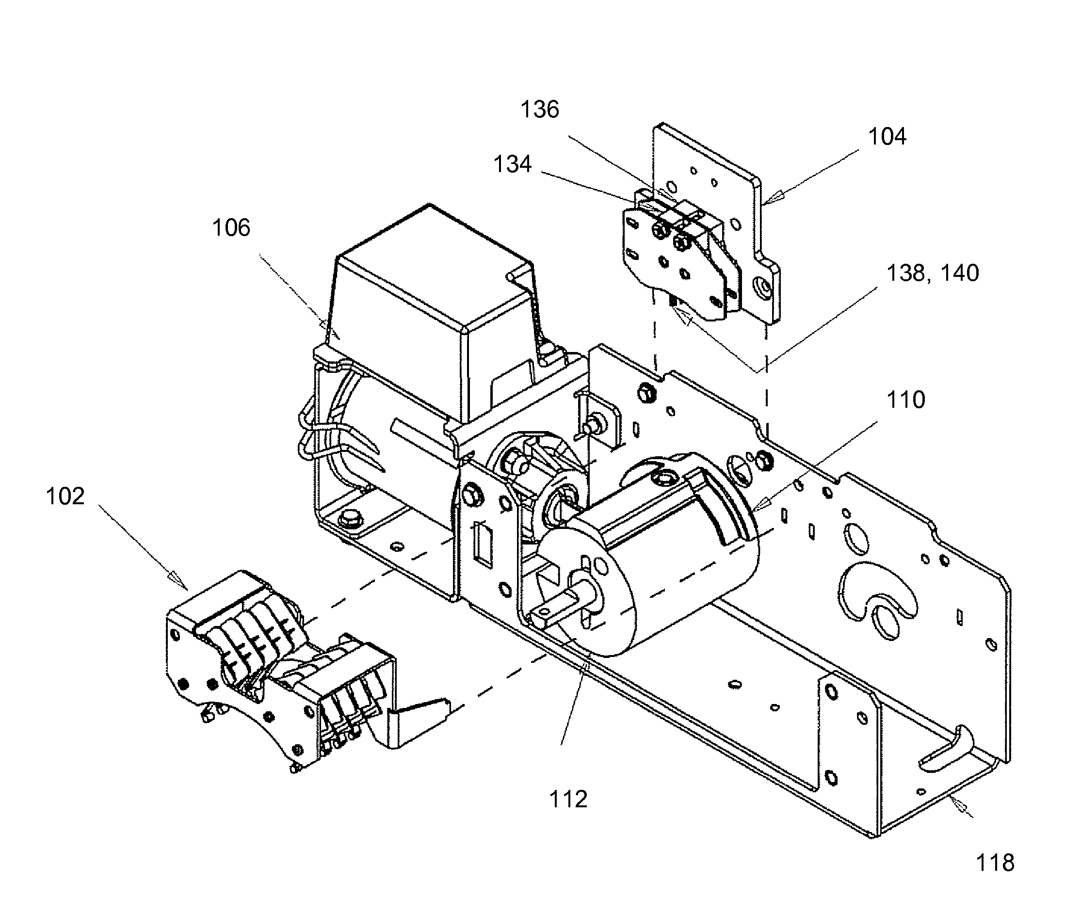
[0031]Referring to FIG. 5, a transfer switch 100 is illustrated according to a preferred arrangement. The transfer switch 100 comprises an auxiliary contacts assembly 102 and solenoid control contacts assembly 104. Both the auxiliary contacts assembly 102 and solenoid control contacts assembly 104 are located adjacent a solenoid actuator 106. Preferably, the contact assemblies 102 and 104 are actuated by a dual purpose actuation cam 110 (illustrated in FIG. 6).

[0032]Referring now to FIG. 6, the actuation cam 110 is attached to a rotating weight 112. Although the rotating weight 112 is illustrated as a weight 112 having a cylindrical shape, alternative shaped weights may also be used. A washer 114 and a screw 116 may be included to secure the actuation cam 110 to the rotating weight 112. Alternatively, in a different arrangement, the actuation cam 110 may be secured to the rotating weight 112 by any other known fastening device.

[0033]In this preferred arrangement, the actuation cam 1...


PUM

PropertyMeasurementUnit
weightaaaaaaaaaa
timeaaaaaaaaaa
poweraaaaaaaaaa

Abstract

An automatic transfer switch includes a solenoid control contacts assembly, an auxiliary contacts assembly, a dual purpose cam attached to a cylindrical shaped weight, and a solenoid actuator. When energized, the solenoid actuator rotates the cylindrical weight and the dual purpose cam actuates both the solenoid control contacts assembly and the auxiliary contacts assembly.

Description

RELATED APPLICATIONS[0001]This application claims priority to provisional application No. 60 / 771,047, filed Feb. 6, 2006.BACKGROUND[0002]1. Field of the Application[0003]This application relates generally to electrical power transfer switches. More specifically, the present application relates to automatic transfer switches.[0004]2. Description of Related Art[0005]In general, a typically available automatic transfer switch consists of a number of components. For example, such transfer switches generally comprise a main switch panel with power contacts, a solenoid actuator, a set of solenoid control contacts, and a set of auxiliary contacts. The solenoid actuator typically is used to close and open the power contacts through a mechanical switching mechanism. The auxiliary contacts are used for position sensing which information is used by an electronic controller. The solenoid control contacts control the amount of time that the solenoid is energized. In addition, the auxiliary conta...

Claims


Application Information

Patent Timeline
Patent Type & Authority Patents(United States)
IPC IPC(8): H01H13/70
CPCH01H3/28H01H9/0066Y10T29/49105H01H2300/018H01H19/62
Inventor MELCHIONNE, JR., ROCCO M.
Owner ASCO POWER TECH LP
Why Eureka
Try Eureka