Image pickup apparatus with noise reduction unit

a pickup apparatus and noise reduction technology, applied in the field of image pickup apparatus, can solve the problems of increasing the number of taps, requiring more taps, and reducing the resolution, and achieve the effects of suppressing random noise, high frame rate moving images, and high resolution still images

Inactive Publication Date: 2011-03-01
PANASONIC CORP
View PDF10 Cites 4 Cited by
  • Summary
  • Abstract
  • Description
  • Claims
  • Application Information

AI Technical Summary

Benefits of technology

[0029]An object of the present invention is to realize an image pickup apparatus that is able to suppress random noise and process high frame rate moving images, and to obtain high resolution still images. A further object of the present invention is to realize such an image pickup apparatus with a simple configuration.

Problems solved by technology

However, raising the amplification factor of the amplifier also amplifies the noise component contained in the charge output from the photoelectric conversion elements.
However, with low pass filtering using a two-dimensional filter as disclosed in patent document 1 or a mixed pixel reading method as disclosed in patent document 2, resolution degradation is a problem.
Also, the random noise suppression effect resulting from low pass filtering using a two-dimensional filter is limited by the number of taps in the filter, thereby requiring more taps to obtain a greater effect.
The problem is that increasing the number of taps increases the circuitry size.
Further, with a cyclic noise reduction method as disclosed in patent document 3, not many frames can be read by the image pickup element per unit of time when still images are shot using an image pickup element with a large number of pixels, thereby reducing the quality of moving images.

Method used


Image

  • Image pickup apparatus with noise reduction unit
  • Image pickup apparatus with noise reduction unit
  • Image pickup apparatus with noise reduction unit

Examples


embodiment 1

[1. Configuration of Image Pickup Apparatus]

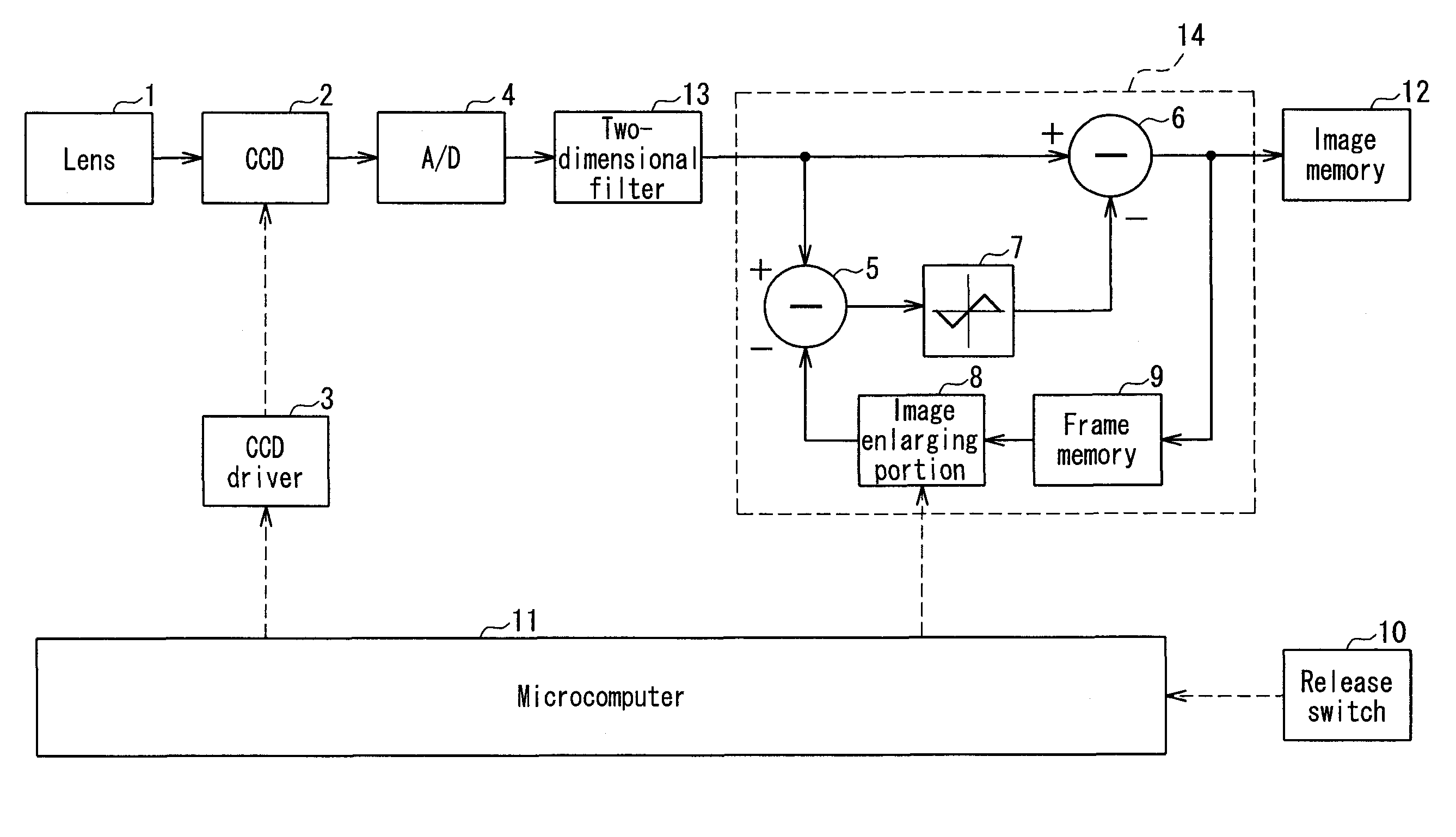
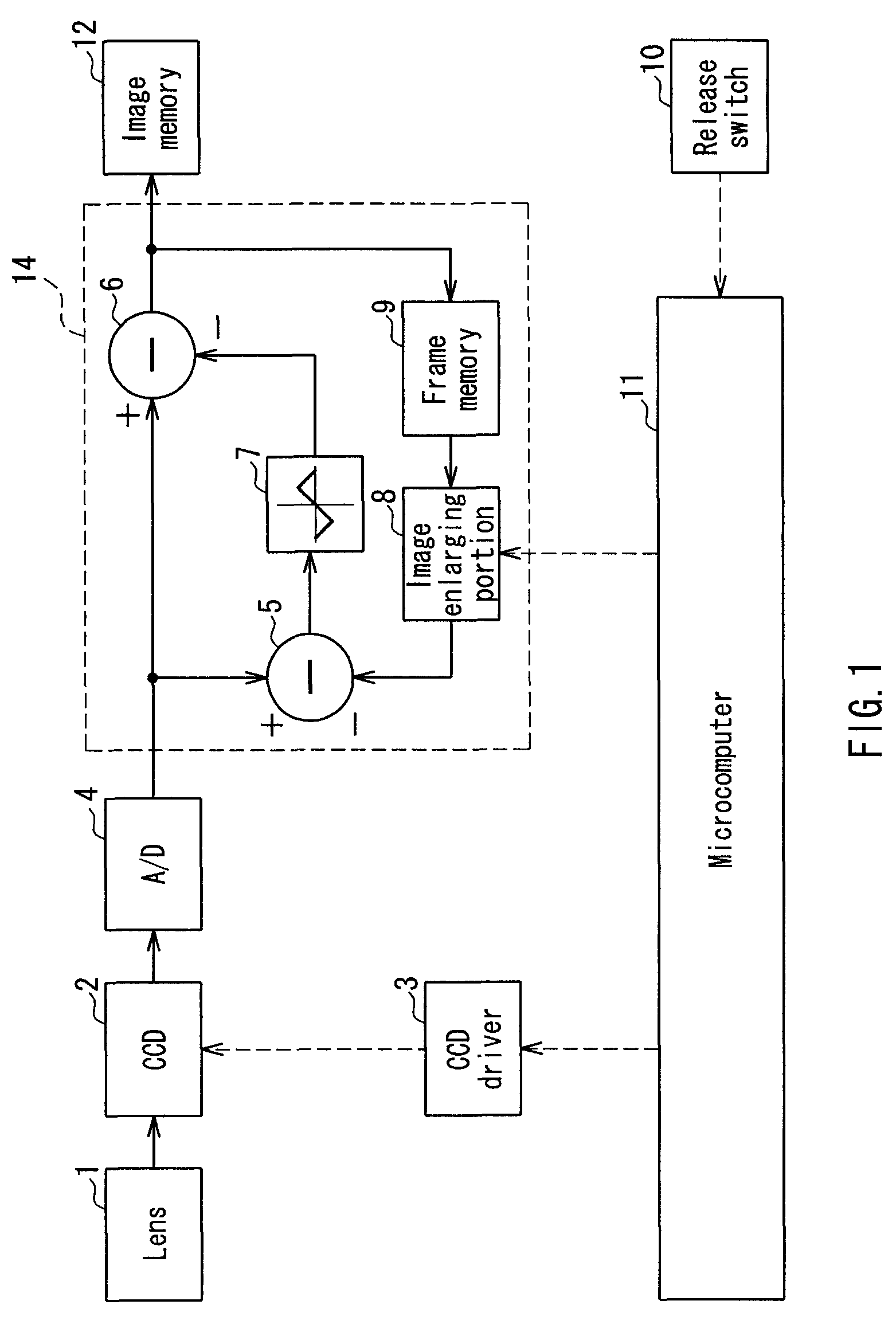
[0052]FIG. 1 is a block diagram showing the configuration of an image pickup apparatus according to embodiment 1. The image pickup apparatus includes a lens 1, a CCD image sensor 2, a CCD driver 3, an analog-digital conversion unit 4 (hereinafter, A / D conversion unit), a release switch 10, a microcomputer 11, an image memory 12, and a noise reduction circuit 14.

[0053]The CCD image sensor 2, which includes a large number of photoelectric conversion elements in a matrix, converts an optical image incident via the lens 1 to an electrical image and outputs the electrical image. The CCD image sensor 2 can operate in pixel mixing mode (first drive mode) or all-pixel reading mode (second drive mode). Pixel mixing mode is a mode in which a plurality of horizontally and vertically arrayed pixels are added and output, and effectively involves decimating the pixels to reduce resolution. All-pixel reading mode is a mode in which pixel signals from all...

embodiment 2

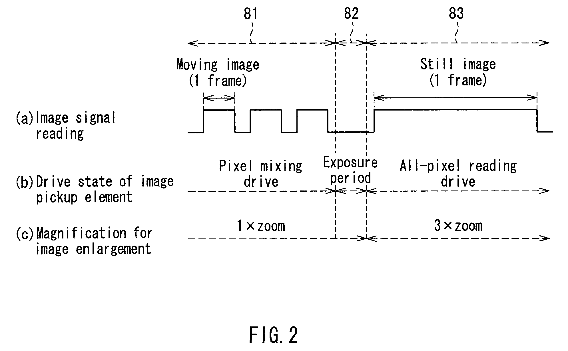
[0082]FIG. 3 is a block diagram showing the configuration of an image pickup apparatus according to embodiment 2. Note that in FIG. 3 the same reference numerals are attached to constituent elements that are similar to the configuration shown in FIG. 1, and a detailed description of these elements will be omitted. The configuration shown in FIG. 3 results from adding a two-dimensional filter 13 to the configuration shown in FIG. 1. The image pickup apparatus of the present embodiment operates based on the timing chart shown in FIG. 2.

[0083]The two-dimensional filter 13 (filtering unit) has the configuration shown in FIG. 16 mentioned above, and adaptively performs low pass filtering based on the correlation between the target pixel and neighboring pixels (8 pixels).

[0084]The operations are described next.

[0085]In period 81 of FIG. 2, the image data that has undergone pixel mixing by the CCD image sensor 2 to decimate the pixels to one-third in the horizontal and vertical directions ...

embodiment 3

[1. Configuration of Image Pickup Apparatus]

[0088]FIG. 4 is a block diagram showing the configuration of an image pickup apparatus according to embodiment 3. Note that in FIG. 4 the same reference numerals are attached to constituent elements that are similar to the configuration shown in FIG. 1, and a detailed description of these elements will be omitted. The configuration shown in FIG. 4 results from adding a decimating portion 15 to the configuration shown in FIG. 1, and includes a CCD image sensor 21 in place of the CCD image sensor 2. The image pickup apparatus of the present embodiment operates based on the timing chart shown in FIG. 2. In the present embodiment, however, FIG. 2(b) shows the operations of the decimating portion 15.

[0089]The CCD image sensor 21, different from the CCD image sensor 2 of embodiment 1, is constituted by an image pickup element that operates only in all-pixel reading mode.

[0090]The decimating portion 15 operates in pixel mixing mode or all-pixel r...


PUM


Abstract

An image pickup apparatus comprises an image pickup element that includes a plurality of photoelectric conversion elements, and is operable in a first drive mode for reading a low resolution image based on an output of the photoelectric conversion elements or a second drive mode for reading a higher resolution image than the low resolution image, a drive unit that drives the image pickup element, a frame memory that stores image data read by the image pickup element in the first drive mode, an image enlarging portion that enlarges an image size of the image data stored in the frame memory, and a noise reduction unit that performs noise reduction on image data read by the image pickup element in the second drive mode, based on the image data enlarged by the image enlarging portion. This configuration enables high frame rate moving images to be obtained. Further, degradation of image resolution can be prevented, and random noise contained in images can be suppressed.

Description

BACKGROUND OF THE INVENTION[0001]1. Field of the Invention[0002]The present invention relates to an image pickup apparatus having a function of suppressing random noise produced by an image pickup element or the like.[0003]2. Description of Related Art[0004]A CCD image sensor, which is an exemplary image pickup element, includes photoelectric conversion elements arranged in a matrix, a transfer unit that transfers charge output from the photoelectric conversion elements, and an amplifier that amplifies the voltage of the charge transferred by the transfer unit and outputs an image signal.[0005]Currently, with image pickup elements widely used in digital still cameras and video cameras, the amount of charge that can be stored in a single photoelectric conversion element is decreasing due to increased miniaturization and higher pixel counts. While pixel sensitivity drops when the amount of stored charge decreases, sensitivity can be raised by increasing the amplification factor of the...

Claims


Application Information

Patent Timeline
Patent Type & Authority Patents(United States)
IPC IPC(8): H04N5/217H04N5/225H04N5/343H04N5/357
CPCH04N5/217H04N5/23245H04N5/347H04N5/357H04N23/81H04N23/667H04N25/46H04N25/60
Inventor TANIZOE, YUKIHIRO
Owner PANASONIC CORP
Why Eureka
Try Eureka