Thermal nonlinearity cell for guiding electromagnetic energy through a nonlinear medium

a nonlinearity cell and electromagnetic energy technology, applied in the field of laser systems, can solve the problems of inability to provide good phase conjugation fidelity of single thin layer thermal cells, inability to project one-layer holograms well to high power scaling, and interference patterns

Active Publication Date: 2011-03-01
RAYTHEON CO
View PDF12 Cites 0 Cited by
  • Summary
  • Abstract
  • Description
  • Claims
  • Application Information

AI Technical Summary

Problems solved by technology

The signal beam propagates through the medium at an angle relative to at least one of the pump beams and thereby creates an interference pattern.
This can be a problem for high power applications.
However, a single thin layer thermal cell usually cannot provide good phase conjugation fidelity due to the insufficient selectivity of a conjugated wave by a thin hologram.
In addition, a one-layer hologram is not well projected to high power scaling because its capability in sustaining high laser power and thermal load in just one layer of absorbing liquid could be limited.
This technique, however, requires a mechanical means for providing the liquid flow, such as pumps, etc., which may be costly to construct and operate.
For high average power operation, the flow velocity and the pressure drop could be too high to be able to project to the desired power scalability.
Practical implementation of this approach relies on good quality optics and multiple surfaces with complex high transmission and / or high reflective coatings, which may lead to excessive losses and compatibility problems with the nonlinear liquid.
Another problem in practical implementation comes from the fact that the liquid layers should be very thin for rapid heat transfer, but should have enough absorption for the thermal nonlinearity mechanism to take place.
A high absorption coefficient in liquid is typically achieved by adding special impurities into the liquid that are absorptive at the laser-wavelength, thus creating a problem with the choice of materials and compatibility with the liquid and its stability.

Method used


Image

  • Thermal nonlinearity cell for guiding electromagnetic energy through a nonlinear medium
  • Thermal nonlinearity cell for guiding electromagnetic energy through a nonlinear medium
  • Thermal nonlinearity cell for guiding electromagnetic energy through a nonlinear medium

Examples


Embodiment Construction

[0018]Illustrative embodiments and exemplary applications will now be described with reference to the accompanying drawings to disclose the advantageous teachings of the present invention.

[0019]While the present invention is described herein with reference to illustrative embodiments for particular applications, it should be understood that the invention is not limited thereto. Those having ordinary skill in the art and access to the teachings provided herein will recognize additional modifications, applications, and embodiments within the scope thereof and additional fields in which the present invention would be of significant utility.

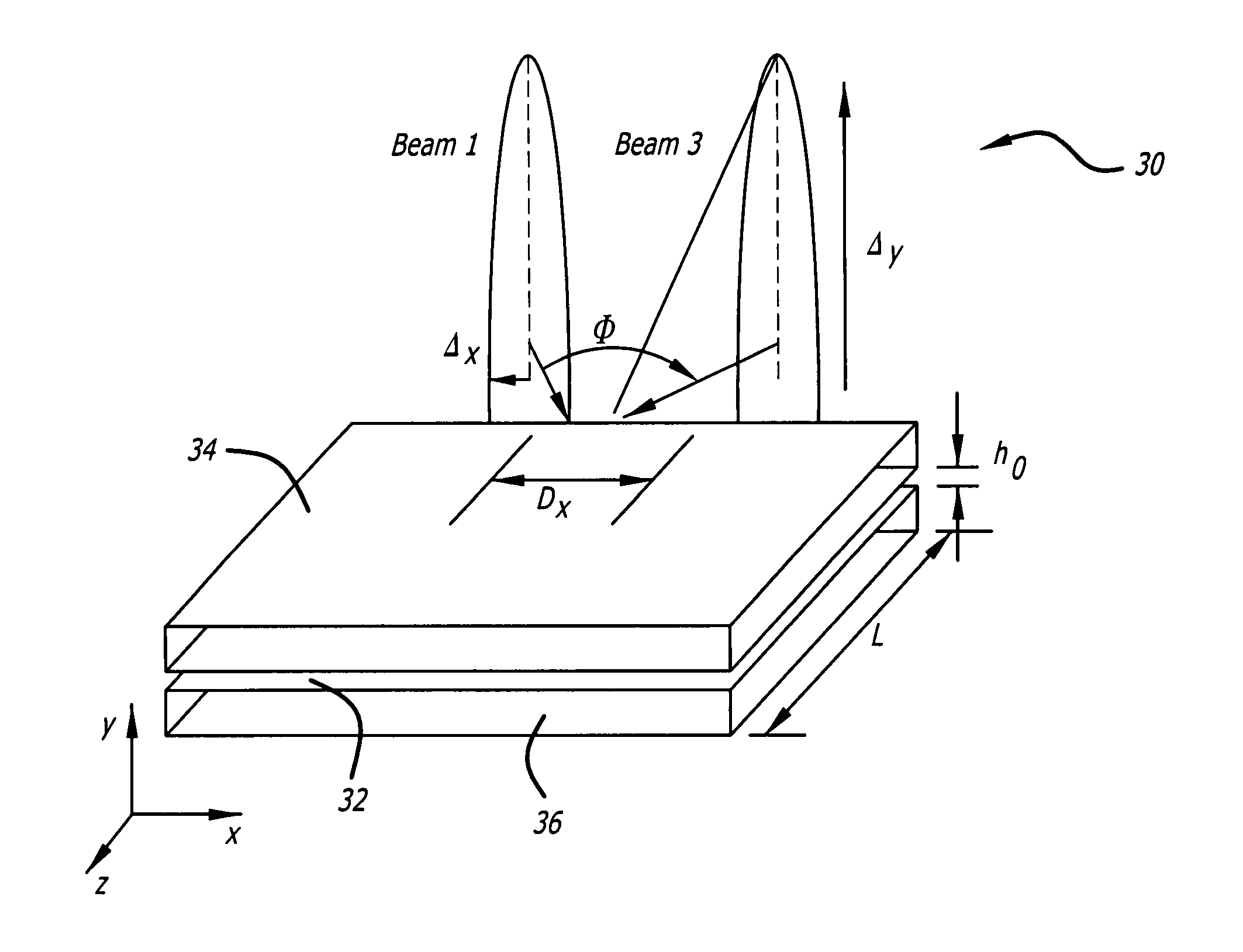
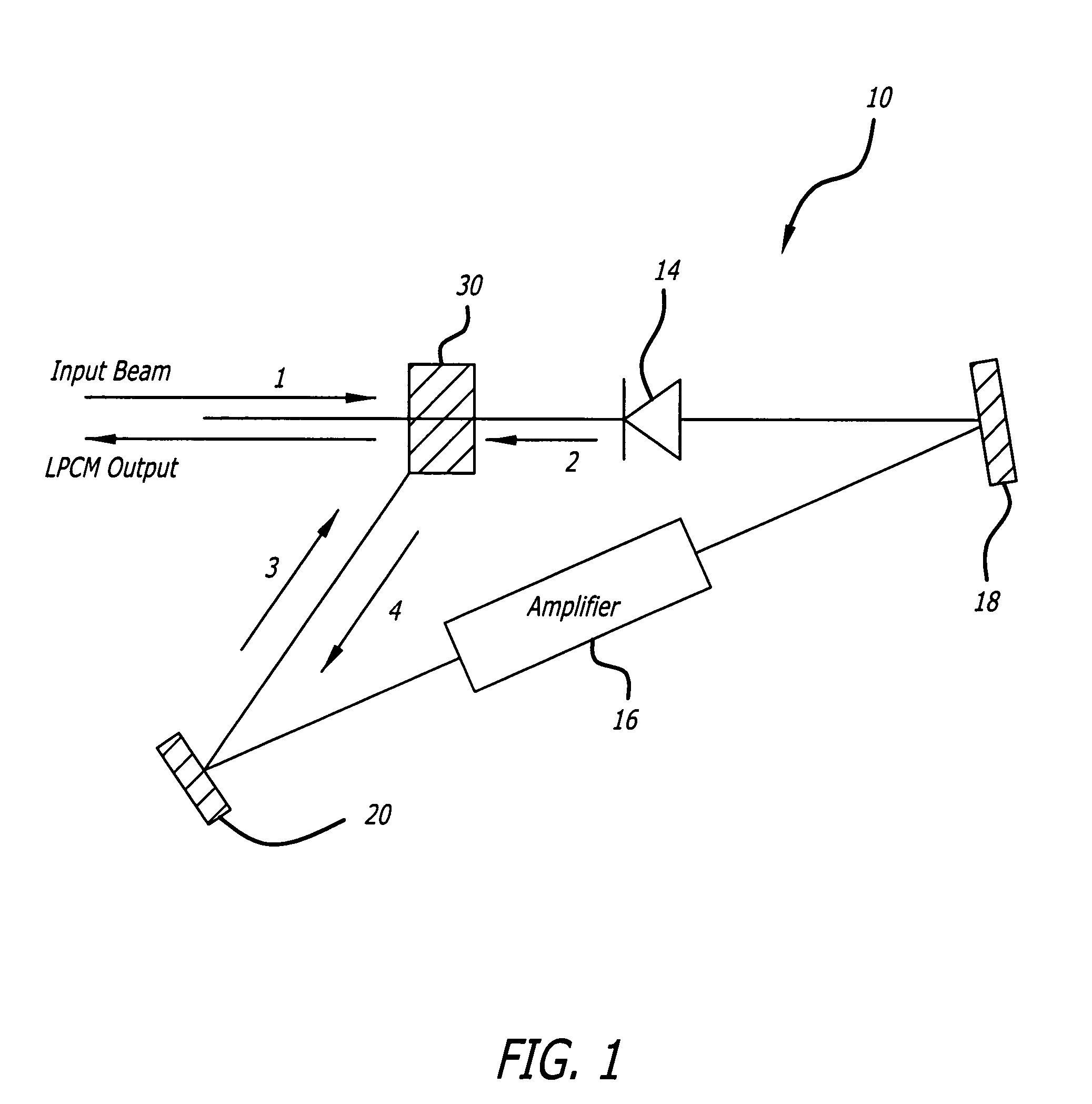
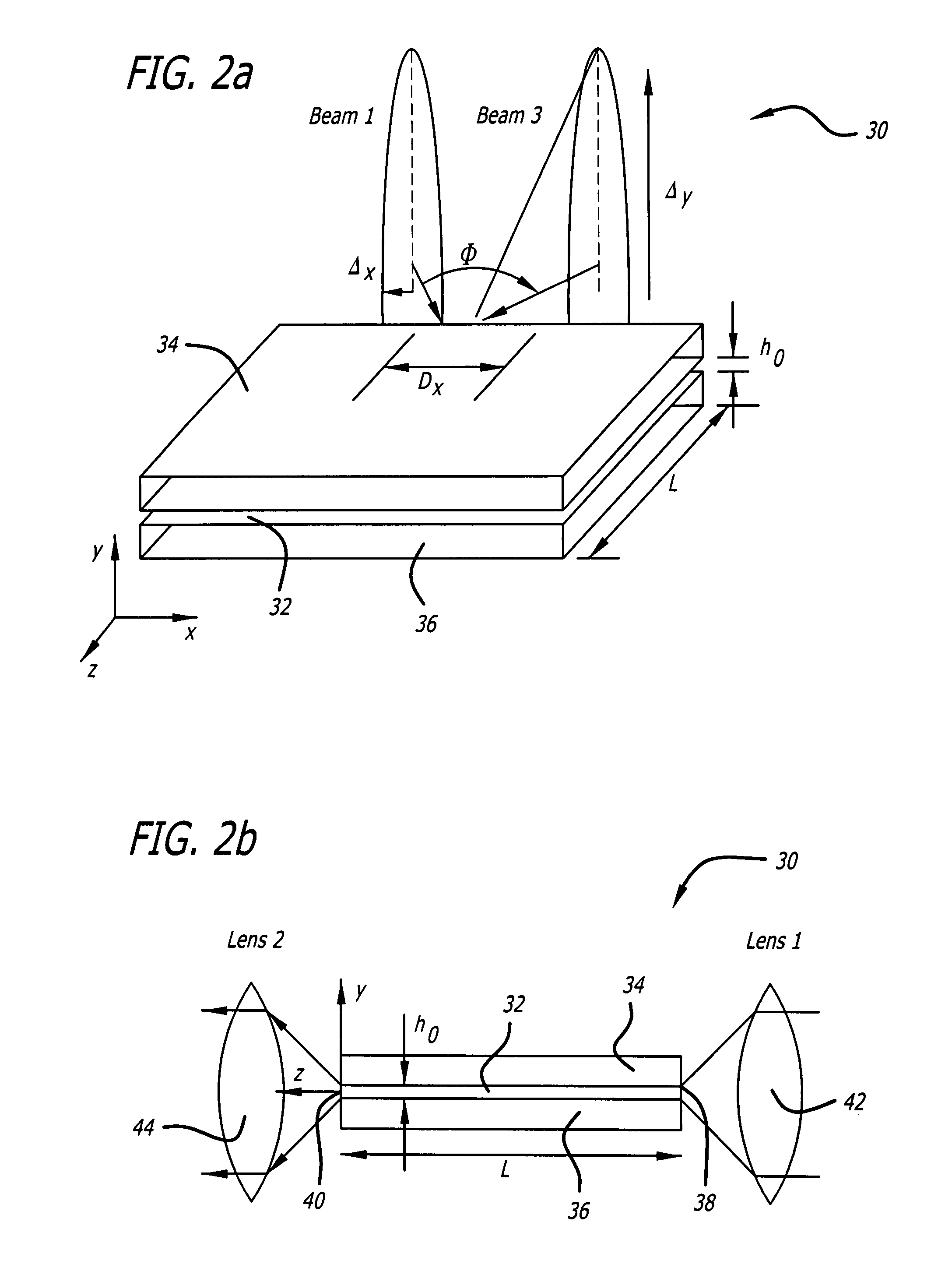
[0020]FIG. 1 is an optical schematic of a loop phase conjugate mirror (LPCM) system 10 that represents a major system for applying a guided thermal nonlinearity cell 30 designed in accordance with an illustrative embodiment of the present teachings. The illustrative system 10 uses the nonlinearity cell 30 in a four-wave mixing (FWM) configuration to ...


PUM


Abstract

A guiding nonlinearity cell. The novel nonlinearity cell includes a nonlinear medium and a waveguide adapted to guide input electromagnetic energy through the nonlinear medium. In an illustrative embodiment, the cell includes a thin layer of a liquid or solid nonlinear medium disposed between two parallel plates adapted to guide energy through the length of the medium by total internal reflection. The plates can be made from a material having a refractive index less than a refractive index of the medium to provide total internal reflection within the liquid, or they can be made from a material matching the refractive index of the medium such that outer walls of the plates provide total internal reflection, allowing energy to leak into the plates.

Description

BACKGROUND OF THE INVENTION[0001]1. Field of the Invention[0002]The present invention relates to laser systems. More specifically, the present invention relates to nonlinear optics and high power lasers.[0003]2. Description of the Related Art[0004]Nonlinearity cells are commonly used in applications such as phase conjugate mirrors to generate real-time holograms. A nonlinearity cell typically includes a window containing one or more layers of a nonlinear optical medium whose optical properties (usually its refractive index) change in response to the presence of light. When an interference pattern formed by two beams of light is applied to the nonlinear medium, the interference pattern is reproduced in the medium as a pattern of high and low refractive index, effectively creating a diffraction grating that is a real-time hologram of the optical interference pattern. The nonlinear medium tracks changes in the interference pattern formed by the two beams such that as the interference p...

Claims


Application Information

Patent Timeline
Patent Type & Authority Patents(United States)
IPC IPC(8): H01S4/00G02B6/10
CPCH01S3/10076H01S3/2308
Inventor BETIN, ALEXANDER A.SHKUNOV, VLADIMIR V.
Owner RAYTHEON CO
Why Eureka
Try Eureka