
Storm panel for protecting windows and doors during high winds

a technology for windows and doors and storm panels, applied in the field of storm panels, can solve problems such as unsatisfactory solutions, and achieve the effects of high strength, high tenacity and high strength

Active Publication Date: 2011-03-08
ADVANCED COMPOSITE STRUCTURES LTD
View PDF67 Cites 20 Cited by
  • Summary
  • Abstract
  • Description
  • Claims
  • Application Information

AI Technical Summary

Benefits of technology

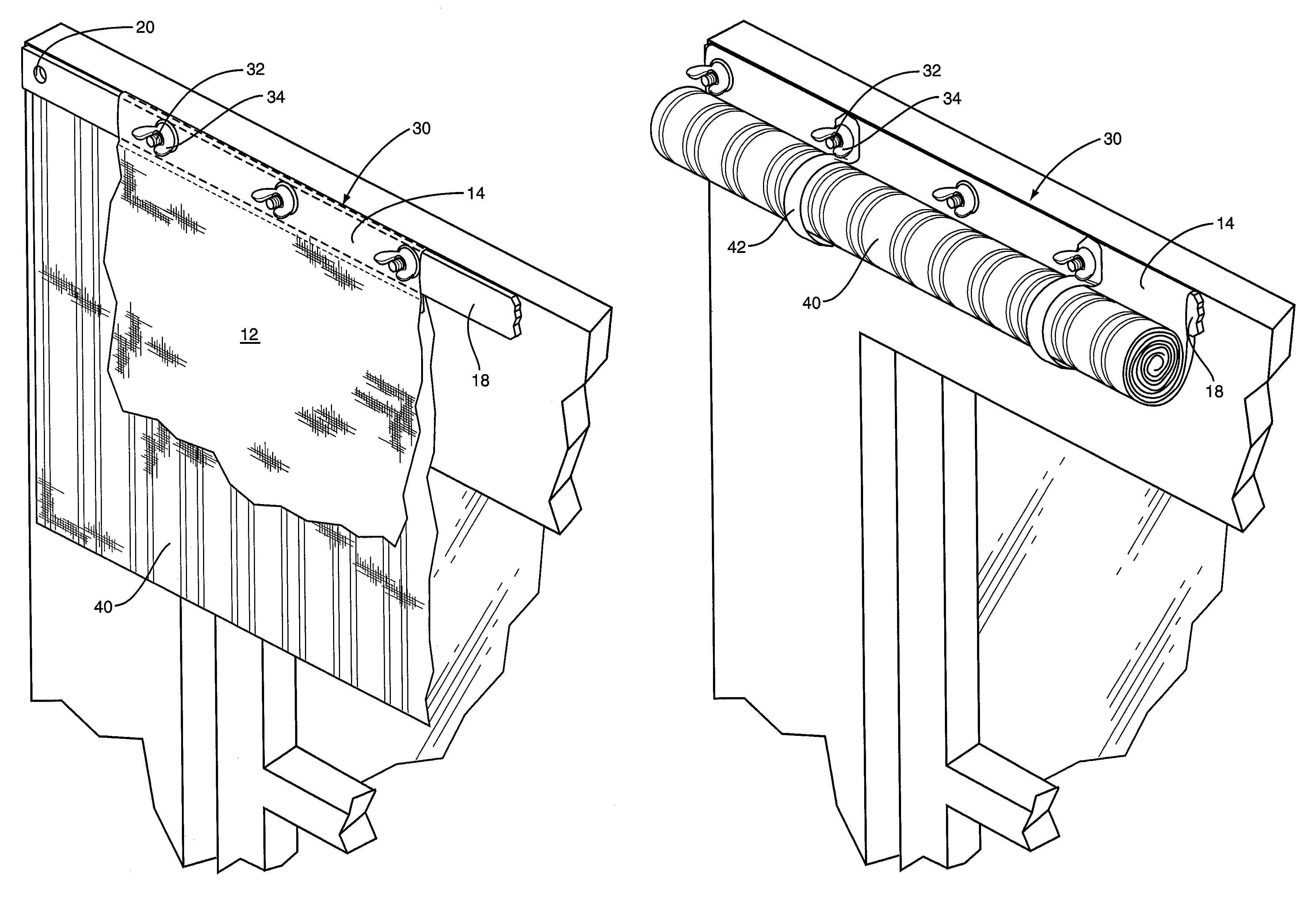
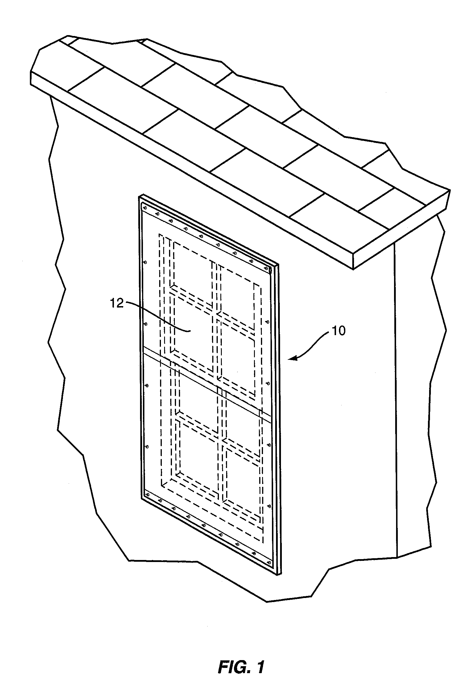
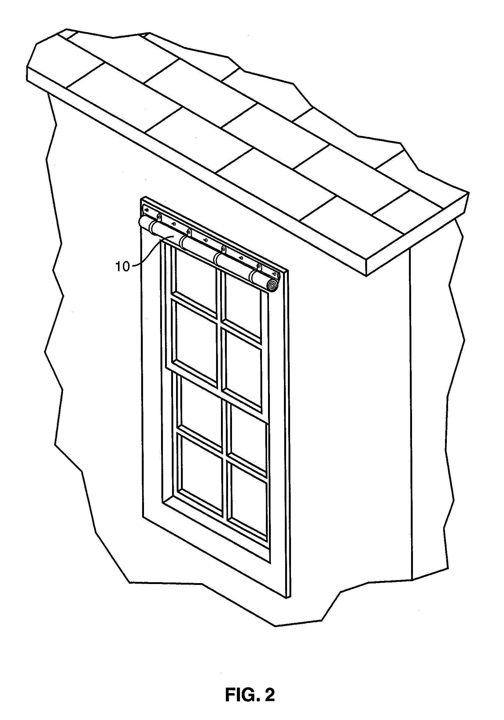
The present invention is a lightweight, translucent panel that can protect window and door openings from debris and airborne objects during hurricane force winds. The panel is made of high strength yarns made from high strength polymeric fibers. The panel has a reinforcing strip along its edges and a series of holes for secure attachment to the building. The panel can be easily stored when not in use and is designed to comply with building codes. The technical effect of the invention is to provide an effective and lightweight solution for protecting window and door openings during hurricanes.

Problems solved by technology

Thus, despite the existence of such storms for many, many years, and despite the existence of materials of many types, including high strength fabrics, no satisfactory solution has been found.

Method used


Image

  • Storm panel for protecting windows and doors during high winds
  • Storm panel for protecting windows and doors during high winds
  • Storm panel for protecting windows and doors during high winds

Examples


example 1

[0038]A flexible composite fabric was formed from a single ply fabric made of ultra high molecular weight, extended chain polyethylene fibers. The fibers were Spectra® 900, 650 denier yarn available from Honeywell International Inc. and had a tenacity of 30.5 g / d. The fabric was in the form of a plain weave woven fabric (style 904 made by Hexcel Reinforcements Corp.), characterized as having a weight of 6.3 oz / yd2 (0.02 g / cm2), 34×34 ends per inch (13.4×13.4 ends per cm), a yarn denier of 650 in both the warp and weft, and a thickness of 17 mils (425 μm). The fabric was laminated on both sides to a low density polyethylene film having a thickness of 1.5 mil (37.5 μm). A 4 mil (100 μm) film of ethylene vinyl acetate was used as a bonding layer between the fabric layer and the two polyethylene film layers. The layers were laminated together by a thermal lamination technique as described in U.S. Pat. Nos. 6,280,546 and 6,818,091.

[0039]The total composite fabric weight was 14.8 oz / yd2 (...

example 2

[0042]A flexible composite fabric was formed from a single ply fabric made of extended chain polyethylene fibers. The fibers were Spectra® 900, 1200 denier yarn available from Honeywell International Inc. and had a tenacity of 30 g / d. The fabric was in the form of a basket weave woven fabric (style 912 made by Hexcel Reinforcements Corp.), characterized as having a weight of 11.3 oz / yd2 (0.044 g / cm2), 34×34 ends per inch (13.4×13.4 ends per cm), a yarn denier of 1200 in both the warp and weft, and a thickness of 28 mils (700 μm). The fabric was laminated on both sides to a low density polyethylene film having a thickness of about 2 mils (10 μm). A 7-8 mil (175-200 μm) film of ethylene vinyl acetate was used as a bonding layer between the fabric and the two polyethylene film layers. The layers were laminated together by a thermal lamination technique as described in U.S. Pat. Nos. 6,280,546 and 6,818,091.

[0043]The total composite fabric weight was 20 oz / yd2 (0.07 g / cm2), and the tota...


PUM


Abstract

A storm panel of high strength fabric is constructed, reinforced, and installed in such a way as to comply with the building codes as a large missile impact system. When not in use, the fabric can be rolled and stored and placed in an attractive cover without disassembly.

Description

BACKGROUND OF THE INVENTION[0001]1. Field of the Invention[0002]This invention relates to a storm panel to protect property against damage caused by high winds and impact from associated flying objects and debris that result from a hurricane or other occurrence.[0003]2. Description of the Related Art[0004]Various devices and materials have been proposed for the protection of building openings (such as windows, doors, and sliding glass doors) from the effects of high winds and flying objects associated with a hurricane or similar event. Some have even been utilized. In the simplest and most often utilized form, sheets of plywood have been nailed, screwed, or otherwise attached to a building as a covering for windows and doors. The user needs to acquire and cut plywood sheets to the proper dimensions to cover the openings and to install them. Because of their appearance, bulkiness and weight, plywood covers are typically installed only when a hurricane or similar incident is imminent....

Claims


Application Information

Patent Timeline
Patent Type & Authority Patents(United States)
IPC IPC(8): A47G5/02E06B9/08E06B3/30A47H1/00
CPCE06B9/02E06B2009/005
Inventor HOLLAND, JOHN E.HOLLAND, CONNIE W.NATHAN, DANIEL M.
Owner ADVANCED COMPOSITE STRUCTURES LTD
Learn More