Endoscope apparatus

a technology of endoscope and endoscope, which is applied in the field of endoscope equipment, can solve the problems of limited focusability and complicated operation, and achieve the effect of reducing the diameter and reducing the diameter of the endoscop

Inactive Publication Date: 2011-03-08
FUJI PHOTO OPTICAL CO LTD
View PDF52 Cites 56 Cited by
  • Summary
  • Abstract
  • Description
  • Claims
  • Application Information

AI Technical Summary

Benefits of technology

[0012]In view of such problems, it is an object of the present invention to provide an endoscope apparatus in which a focused enlarged image can be acquired automatically and easily by arranging an automatic focusing mechanism efficiently in a distal end of a small diameter independently from an optical magnification power change mechanism.
[0015]According to the structure in the first aspect of the invention, with the provision of the focus adjusting movable lens for driving with the rapid actuator separately from the power changing movable lens, fine focusing can be achieved automatically.
[0017]According to the endoscope apparatus of the present invention, while the power changing movable lens is driven by the linear transmission member, the focus adjusting movable lens is driven by the compact actuator arranged in the distal end. Therefore, the automatic focusing mechanism, which is independent from the optical magnification power change mechanism, is arranged efficiently in the distal end of reduced diameter, and a focused enlarged image can be acquired automatically and easily.
[0018]According to the structure in the second aspect of the invention, since the automatic focusing control is performed without using the position detection sensor or the like, reduction of the diameter of the endoscope is advantageously achieved.

Problems solved by technology

However, in an enlarged position, focusability is limited due to the observational depth.
In other words, in the related art, when being out of focus, it is necessary to perform focus adjustment operation by minutely moving the distal end of the endoscope for changing the distance with respect to the object to be observed, and such an operation is quite complicated.

Method used


Image

  • Endoscope apparatus
  • Endoscope apparatus
  • Endoscope apparatus

Examples


Embodiment Construction

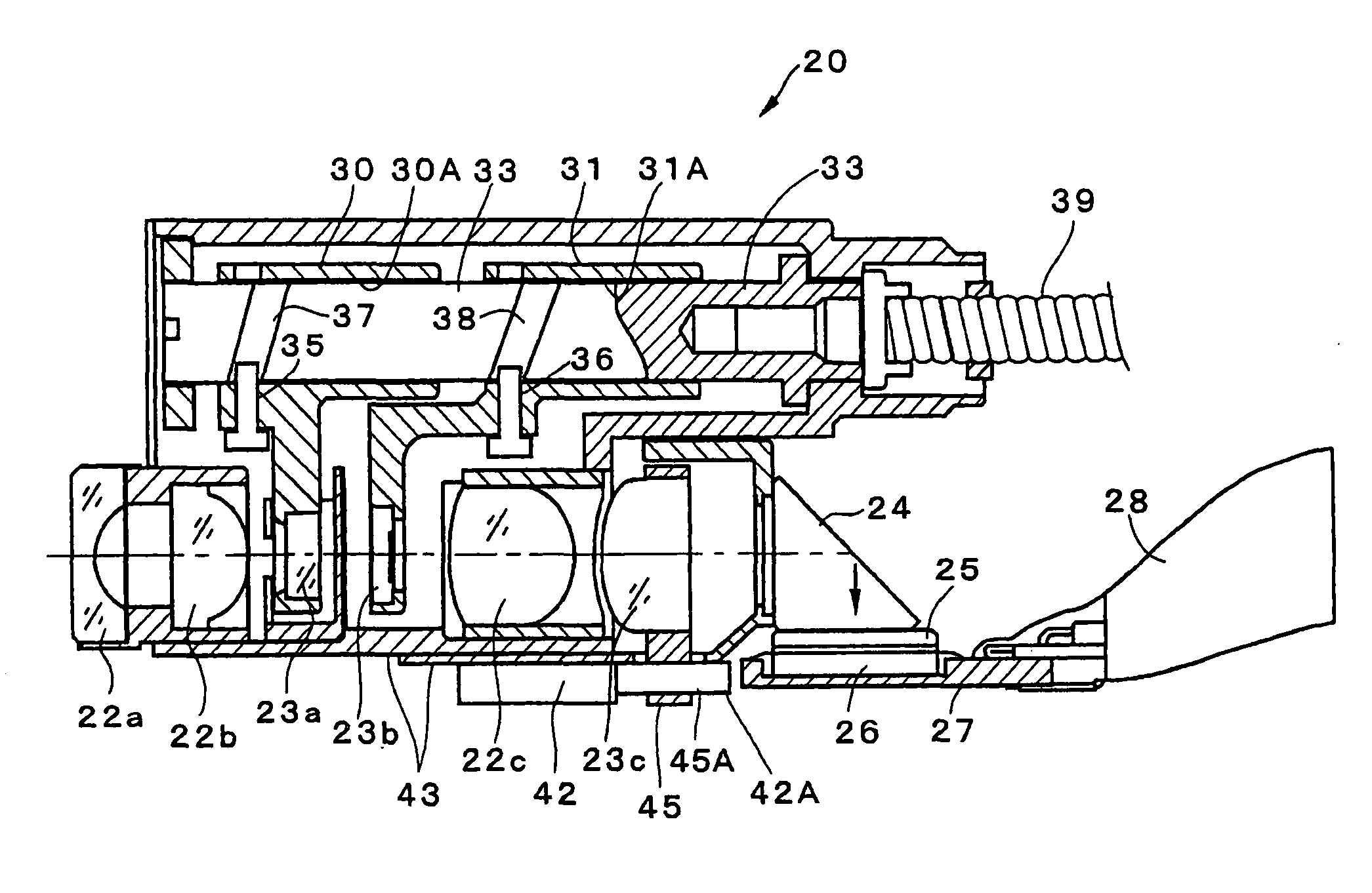
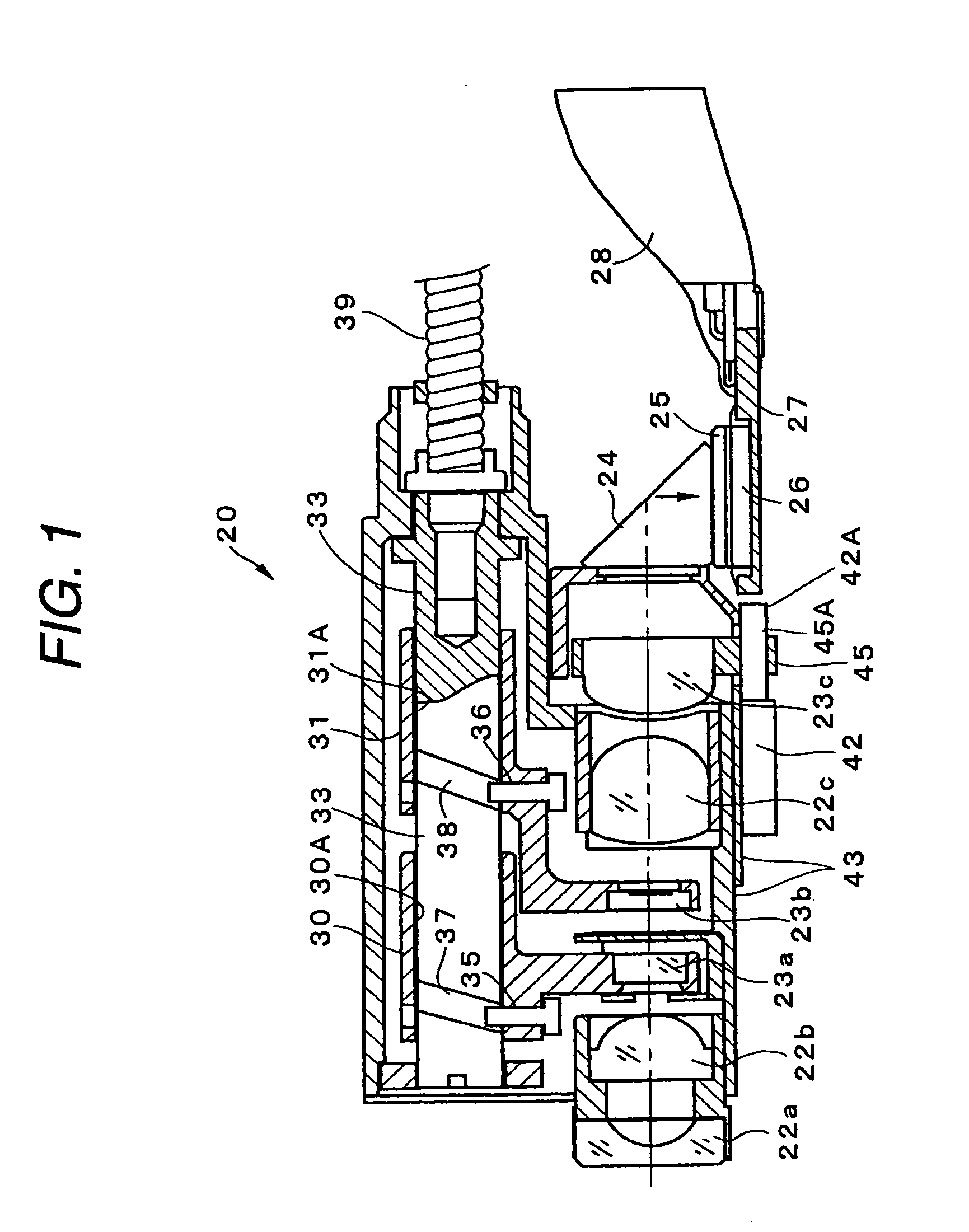
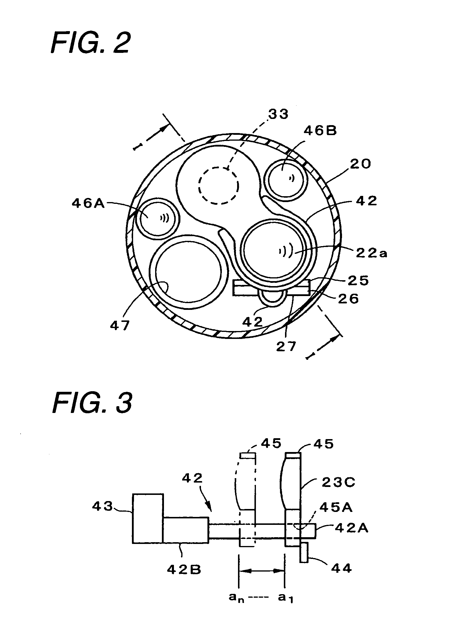
[0025]A structure of an electronic endoscope apparatus according to an embodiment is shown in FIG. 1 and FIG. 4. FIG. 1 shows the structure of a distal end of an endoscope with a portion other than a prism and an image pickup device in cross-section taken along the line I-I in FIG. 2. In FIG. 1, an observation window (lens) 22a, a fixed lens 22b, a first movable lens 23a and a second movable lens 23b for changing the magnification power that are each configured as a varifocal lens, a fixed lens 22c and a third movable lens 23c for focusing are arranged in sequence from the front as an objective optical system at a distal end 20 of the electronic endoscope (scope). A CCD 26 which is a solid state image pickup device is arranged on the backside of the third movable lens 23c with the intermediary of a prism 24 and a cover glass 25. Signals picked up by the CCD 26 are supplied to a processor device via a circuit board 27 and a signal line 28.

[0026]The first movable lens 23a is held by a...


PUM


Abstract

An endoscope apparatus comprises: an insertion section including a distal end; a power changing movable lens that makes observational magnification variable, the power changing movable lens being movably built in an objective optical system provided at the distal end; a linear transmission member that drives the power changing movable lens, the linear transmission member being disposed from a drive section provided at a position other than the insertion section to the distal end; a focus adjusting movable lens that achieves automatic focusing function, the focus adjusting movable lens being movably built in the objective optical system separately from the power changing movable lens; and an actuator that drives the focus adjusting movable lens, the actuator being arranged in the distal end.

Description

BACKGROUND OF THE INVENTION[0001]1. Field of the Invention[0002]The present invention relates to an endoscope apparatus and, in particular, to a structure of an endoscope that performs automatic focus control simultaneously with acquisition of an optically enlarged image of an object to be observed.[0003]2. Description of the Related Art[0004]A electronic endoscope apparatus includes an electronic endoscope (scope) having a CCD (Charge Coupled Device) and the like, which is a solid-state image pickup device, at a distal end thereof, a processor device, and a light source device, and displays an image of an object to be observed on a monitor by picking up an image of an object to be observed by the solid-state image pickup device on the basis of light illumination from the light source device and performing image processing with respect to picture signals by the processor device.[0005]FIG. 6 shows a structure of a distal end of an endoscope with an objective lens moving mechanism in ...

Claims


Application Information

Patent Timeline
Patent Type & Authority Patents(United States)
IPC IPC(8): A61B1/04
CPCA61B1/00096A61B1/00188A61B1/05
Inventor MINAMI, ITSUJI
Owner FUJI PHOTO OPTICAL CO LTD
Why Eureka
Try Eureka