Flip chip device having soldered metal posts by surface mounting

Inactive Publication Date: 2011-03-08
POWERTECH TECHNOLOGY
View PDF1 Cites 44 Cited by
  • Summary
  • Abstract
  • Description
  • Claims
  • Application Information

AI Technical Summary

Benefits of technology

[0009]The main purpose of the present invention is to provide a semiconductor flip-chip assembly having MPS-C2 structure where the existing SMT mounter with poor alignment accuracy

Problems solved by technology

However, the solder balls are completely melt under reflow temperature which can not maintain a specific gap between the bumped chip and the substrate, moreover, the solder balls after reflow are spherical with the contour extending outside the corresponding connection pads.
However, as shown in FIG. 5, when the displacement tolerance δ of the chip 120 is greater than half of the width, W, of the bonding fingers 111, i.e., δ>½ W, any portions of the metal posts 121 can not be aligned to the virtual central line of the corresponding bonding fingers 111 leading to alignment failure.
Therefore, in the conventional MPS-C2 technologies, the displacement tolerance δ of a b

Method used


Image

  • Flip chip device having soldered metal posts by surface mounting
  • Flip chip device having soldered metal posts by surface mounting
  • Flip chip device having soldered metal posts by surface mounting

Examples


Embodiment Construction

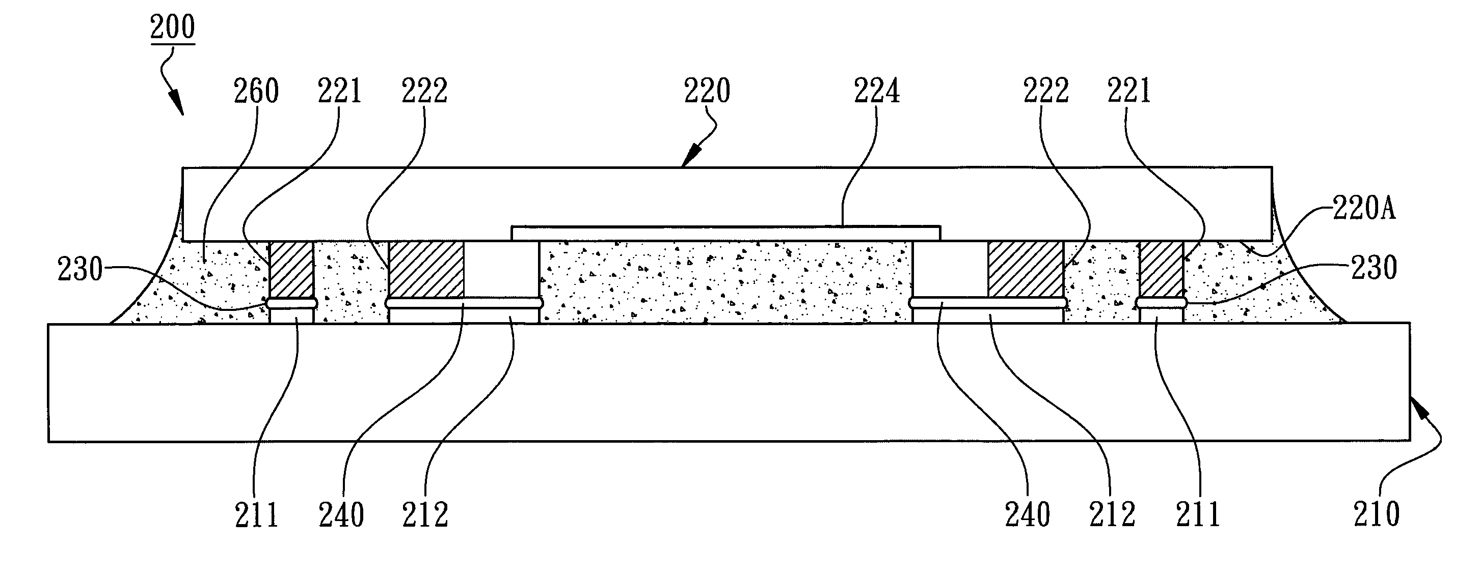
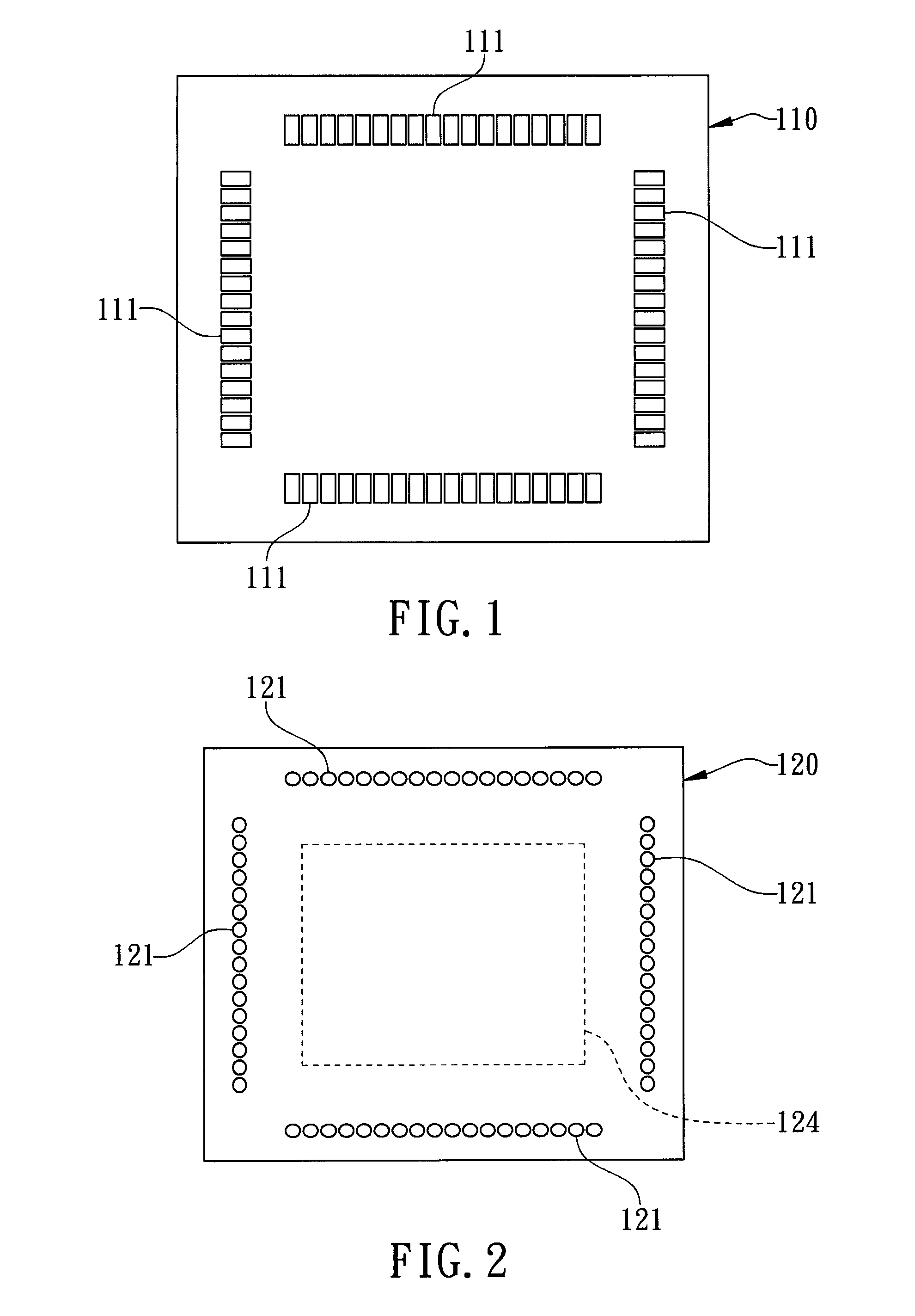
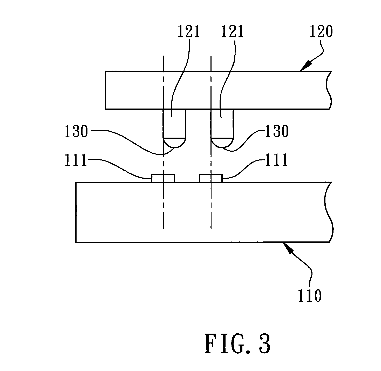
[0030]With reference to the attached drawings, the present invention is described by means of the embodiment(s) below where the attached drawings are simplified for illustration purposes only to illustrate the structures or methods of the present invention by describing the relationships between the components and assembly in the present invention. Therefore, the components shown in the figures are not expressed with the actual numbers, actual shapes, actual dimensions, nor with the actual ratio. Some of the dimensions or dimension ratios have been enlarged or simplified to provide a better illustration. The actual numbers, actual shapes, or actual dimension ratios can be selectively designed and disposed and the detail component layouts may be more complicated.

[0031]According to the first embodiment of the present invention, a semiconductor device having MPS-C2 structure is illustrated in FIG. 7 for a cross-sectional view. A semiconductor flip-chip assembly 200 primarily comprises ...


PUM


Abstract

A disclosed semiconductor device having MPS-C2 (Metal Post Solder-Chip Connection) structure can be mounted on a PCB by an SMT mounter. A chip is disposed on a substrate. The substrate has a plurality of connecting pads and a plurality of accessory pads, and the chip has a plurality of corresponding metal posts and a plurality of accessory bumps. The dimensions on the soldered flat tops of the accessory bumps are corresponding to the soldered areas of the accessory pads where each soldered flat top has a plurality of angular corners and an edge between two adjacent angular corners where the length of the edge is twice greater than the pad pitch. Therefore, the displaced or rotational displaced metal posts can be pulled back and self-aligned during reflow processes so that an SMT mounter with poor alignment accuracy can be implemented for flip-chip bonding the semiconductor device having MPS-C2 structure to replace the conventional expensive flip-chip die bonder and to achieve higher productivity. Furthermore, the shape of the flat top surfaces of the metal posts does not have to match with the shape of the connecting pads.

Description

FIELD OF THE INVENTION[0001]The present invention relates to a semiconductor device, and more particularly to a semiconductor flip-chip assembly having MPS-C2 (Metal Post Solder-Chip Connection) structure.BACKGROUND OF THE INVENTION[0002]The conventional flip-chip bonding technology is related to dispose a plurality of bumps such as solder balls on an active surface of a chip, then the bumps are electrically and mechanically jointed to the corresponding connection pads of a substrate or a printed circuit board by flipping, attaching, and reflow processes to complete a flip chip assembly. When comparing to the conventional electrical connections of wire bonding, flip chip technologies can be implemented in semiconductor packages with high pin counts to provide shorter electrical connections between bumped chips and substrates with good signal qualities at higher operation frequencies. Traditionally, the solder balls are electrically and mechanically connected to the substrate by refl...

Claims


Application Information

Patent Timeline
IPC IPC(8): H01L23/48
CPCH01L23/49838H01L24/13H01L24/14H01L24/17H01L24/81H01L2224/06051H01L2924/014H01L2924/01074H01L2924/0105H01L2924/01047H01L2924/01033H01L2924/01006H01L2924/01005H01L2924/00013H01L2924/01082H01L2924/01079H01L2924/01078H01L2224/0401H01L2224/0603H01L2224/13013H01L2224/13014H01L2224/13015H01L2224/1308H01L2224/13082H01L2224/13111H01L2224/13144H01L2224/13147H01L2224/1403H01L2224/14051H01L2224/14131H01L2224/14135H01L2224/14177H01L2224/14179H01L2224/81121H01L2224/81136H01L2224/81143H01L2224/81801H01L2924/01029H01L2924/00014H01L2224/13099H01L2224/141
Inventor HSU, HUNG-HSINHSU, JUI-CHING
Owner POWERTECH TECHNOLOGY
Why Eureka
Try Eureka