Die cushion controller of press machine

a technology of die cushion and press machine, which is applied in the direction of shaping safety devices, forging/pressing/hammering apparatus, forging presses, etc., can solve the problem that the workpiece cannot be reliably held there, and achieve the effect of more reliable elimination of shrinkag

Active Publication Date: 2011-03-15
KOMATSU IND CORP
View PDF10 Cites 5 Cited by
  • Summary
  • Abstract
  • Description
  • Claims
  • Application Information

AI Technical Summary

Benefits of technology

[0009]When the slide reaches the bottom dead center position, the die-cushion pad follows the slide and moves downward to also stop at its own bottom dead center position. At the bottom dead center position, shrinkages are present on the die-cushion pad and the like. As a solution, according to the aspect of the present invention, the cushion pad is moved downward from the its own bottom dead center position by the predetermined escape height by the position command signal from the escape-position-signal outputting section immediately after the slide has reaches the bottom dead center. With this arrangement, by the downward movement of the die-cushion pad to the escape position, the shrinkages generated due to the loading from the slide can be eliminated. Thus, when the loading is removed by the upward movement of the slide, bouncing of the workpiece at the time of bottom dead center locking, which is attributed to restoration to the original by the shrunk die-cushion pad and the like, can be reliably prevented.
[0010]Since the die-cushion pad is controlled to escape based on the press signal outputted when the slide reaches the bottom dead center, the die cushion does not move downward to the escape position before the slide reaches the bottom dead center or after the upward movement of the slide is started. The escaping of the die-cushion pad can be reliably conducted, thereby reliably preventing the processing or bouncing of the workpiece.
[0012]According to the aspect of the present invention, the escape position of the die-cushion pad is determined not based on the bottom dead center position given as the target position value but based on the bottom dead center position at which the die-cushion pad actually stops. Thus, even if the actual bottom dead center position is fluctuated due to thickness errors or processing errors of the workpiece, the escape position can be uniformly determined based on the bottom dead center without being affected by such fluctuation, thereby contributing to more reliable elimination of the shrinkages.

Problems solved by technology

Thus, when the bottom dead center locking is conducted in the above state, a workpiece bounces therefrom as soon as the loading applied on the die cushion is removed due to the upward movement of the slide, and the workpiece cannot be reliably held thereon.

Method used


Image

  • Die cushion controller of press machine
  • Die cushion controller of press machine
  • Die cushion controller of press machine

Examples


Embodiment Construction

[0024]Next, embodiment(s) of a die-cushion controlling device according to the present invention will be described with reference to the attached drawings.

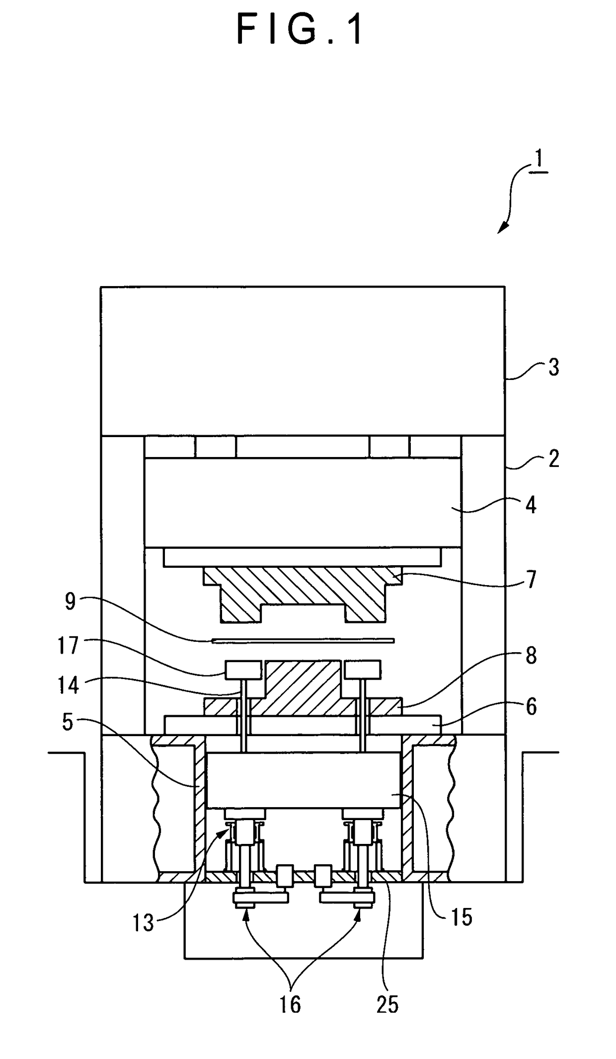
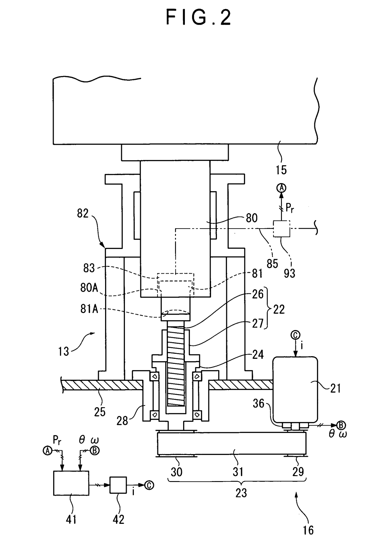
[0025]FIG. 1 schematically shows an arrangement of a press machine according to an embodiment of the present invention. FIG. 2 schematically shows an arrangement of a die cushion 13 according to a first embodiment of the present invention.

[0026]A press machine 1 shown in FIG. 1 includes: a slide 4 supported by a body frame 2 to be movable up and down, and driven to move up and down by a slide driving mechanism 3; and a bolster 6 disposed to face the slide 4, and mounted on a bed 5. A lower surface of the slide 4 is attached with an upper die 7 while an upper surface of the bolster 6 is attached with a lower die 8. With this arrangement, a workpiece 9 placed between the upper die 7 and the lower die 8 experiences press work (drawing) with the slide 4 moved up and down.

[0027]Among the above arrangement, the bed 5 houses a die cushio...


PUM

PropertyMeasurementUnit
escape height Δhaaaaaaaaaa
speedaaaaaaaaaa
currentaaaaaaaaaa

Abstract

A die-cushion controlling device includes a position-command-signal outputting section for outputting a position command signal of a die-cushion pad; a position detecting section for detecting a position of the die-cushion pad; a position comparing section for outputting a position deviation signal corresponding to a deviation between a target position value based on the position command signal and a position detection value based on a position detection signal; a position controlling section for outputting a position-speed command signal based on the position deviation signal; a speed controlling section for outputting a motor-current command signal based on the position-speed command signal; a servo amplifier for generating a current corresponding to the motor-current command signal; and an escape-position-command-signal outputting section for outputting a position command signal for commanding the die-cushion pad to escape from a bottom dead center position based on a press signal outputted when a slide has reached a bottom dead center.

Description

[0001]This application is a U.S. National Phase Application under 35 USC 371 of International Application PCT / JP2007 / 053476 filed Feb. 26, 2007.TECHNICAL FIELD[0002]The present invention relates to a die-cushion controlling device for a press machine used for drawing or the like, the die-cushion controlling device controlling operations of a die-cushion pad in synchronization with operations of a slide.BACKGROUND ART[0003]As a die-cushion controlling device for controlling elevating operations of a die-cushion pad driven by a servo motor, a die-cushion controlling device proposed in, for instance, Patent Document 1 has been conventionally known. According to the die-cushion controlling device disclosed in Patent Document 1, a cushion stroke of a die cushion is controlled by a position control until an upper die of a slide contacts a die-cushion pad with a workpiece sandwiched therebetween. On detecting a change in a current of a servo motor when loading starts to be applied on the d...

Claims


Application Information

Patent Timeline
Patent Type & Authority Patents(United States)
IPC IPC(8): B21C51/00B21J9/18
CPCB21D24/10
Inventor SUZUKI, YUICHI
Owner KOMATSU IND CORP
Why Eureka
Try Eureka