Strainer and control valve

a technology applied in the direction of valve housings, separation processes, filtration separation, etc., can solve the problems of controlling valves that lock or damage control valves, and achieve the effect of improving seals, reducing the yield of strainers and sleeves meeting specifications, and increasing the cost of control valves

Inactive Publication Date: 2011-03-15
AISIN AW CO LTD
View PDF13 Cites 5 Cited by
  • Summary
  • Abstract
  • Description
  • Claims
  • Application Information

AI Technical Summary

Benefits of technology

[0005]However, in the conventional control valve described above, a gap communicating with the port may be formed between the strainer and the strainer attachment portion if the inner peripheral surface of the strainer and the outer peripheral surface of the strainer attachment portion cannot be fitted together sufficiently tight, and foreign matter may infiltrate the control valve through that gap. To improve the seal, the tolerance between the radial dimension and axial dimension of the strainer and the axial dimension and radial dimension of the strainer attachment portion may be strictly set. In this case, however, the yield of strainers and sleeves meeting specifications is correspondingly lowered, and the cost of the control valve is increased.

Problems solved by technology

When foreign matter such as iron powder infiltrates a gap between the sleeve and the spool, it may cause the control valve to lock or damage the control valve.

Method used


Image

  • Strainer and control valve
  • Strainer and control valve
  • Strainer and control valve

Examples


first embodiment

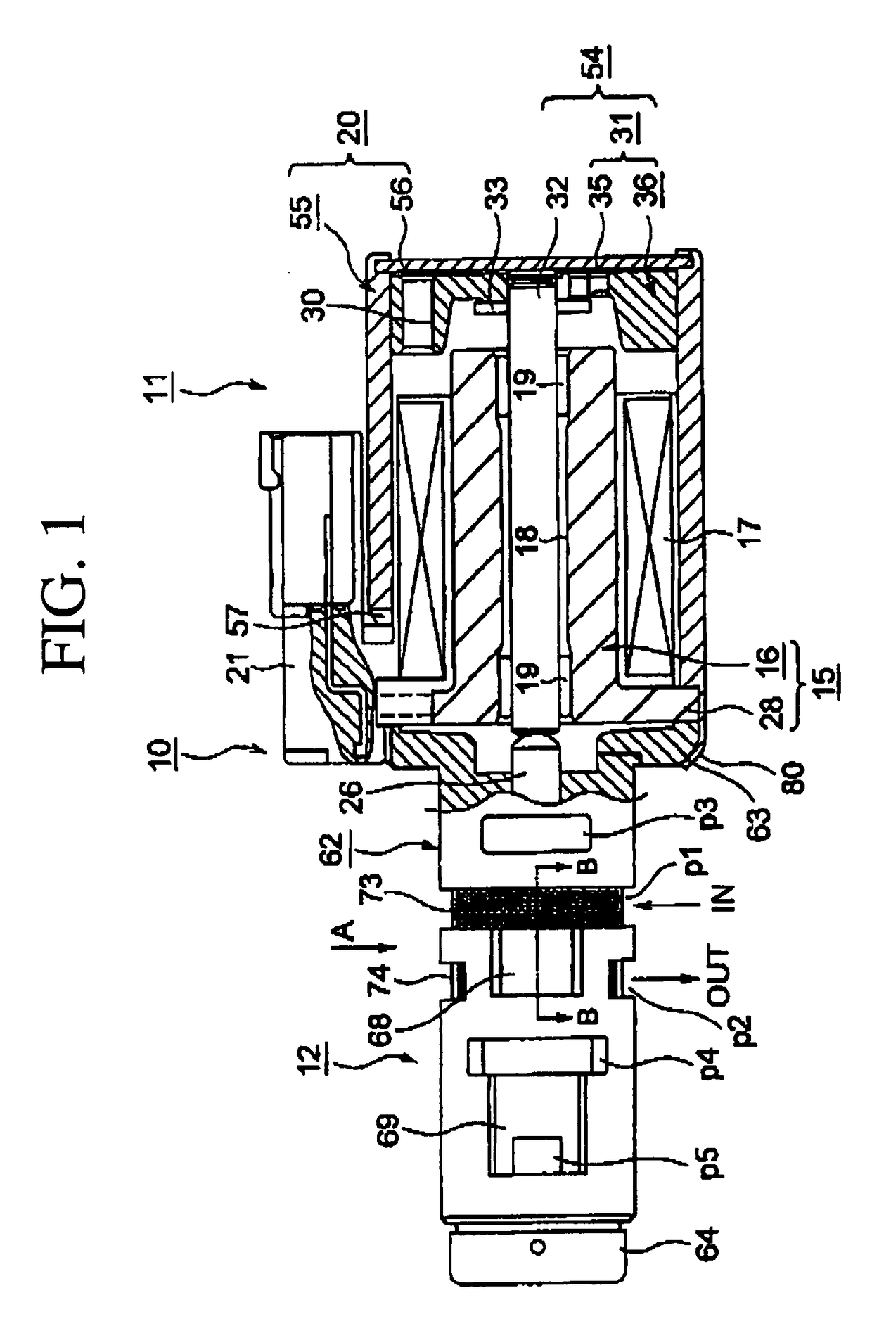
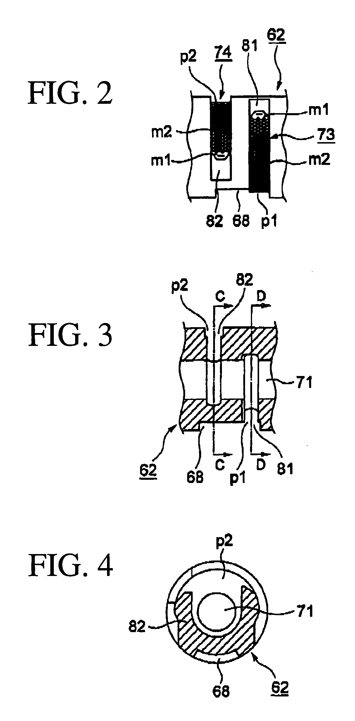
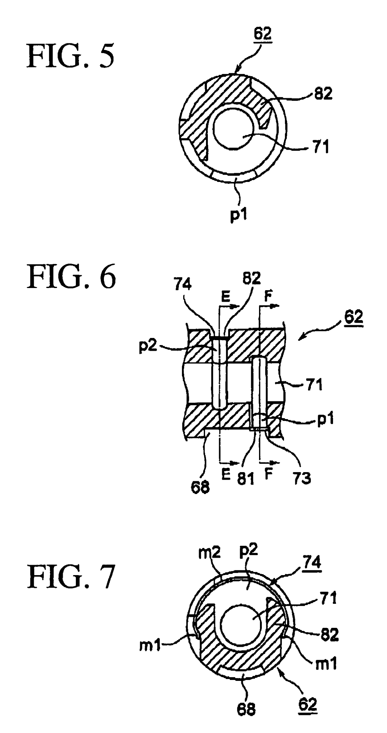
[0032]FIGS. 1-6 show a linear solenoid valve 10 according to the present invention. The linear solenoid valve 10 is connected to a line pressure oil passage or the like in a hydraulic circuit of an automatic transmission via a regulator valve, not shown in the drawing. Oil pressure from an oil pump is regulated by the regulator valve, and this regulated pressure is supplied to the linear solenoid valve 10 as input pressure. The linear solenoid valve 10 is activated by current supplied by a control device, not shown in the drawing, to generate an oil pressure corresponding to the current as a predetermined output pressure (pilot pressure), and to supply the output pressure to a hydraulic servo as control pressure. The hydraulic servo operates to engage and disengage a friction engagement element which is a clutch in this embodiment. The control pressure is supplied to the hydraulic servo according to a predetermined hydraulic pressure pattern for engagement and disengagement of the c...

second embodiment

[0068]In the second embodiment, the coil 17 is formed of a winding 100. A tubular member 101 serves as a first end yoke and is disposed adjacent and radially inward of the coil 17, and extending rearward (toward the right in the drawing) from a predetermined position axially central of the coil 17. An annular end portion 102 serves as a second end yoke and is disposed adjacent the front end (the left end in the drawing) of the coil 17.

[0069]Further, a tubular body 103 including a tubular portion 105 and an annular flange portion 106, formed at the front end of the tubular portion 105 and extending radially outward, with the tubular portion 105 extending within the interior of the coil 17. A plunger 114 is mounted within tubular member 101 and tubular portion 105 for sliding movement left-right in the drawing, radially inward from the end portions 101, 102 and the tubular body 103.

[0070]Next, a third embodiment of the present invention will be described with reference to FIG. 13. Not...

third embodiment

[0071]In this third embodiment, ribs 97, 98 serving as first reinforcement members are formed at a predetermined location on the outer surfaces of respective engagement portions m1. In this embodiment the predetermined location is where the engagement portion curves inward, and the ribs 97, 98 project radially outward. The ribs 97, 98 extend over a predetermined length of the circumferential dimension of the strainer 73, and serve to increase the strength of the engagement portions m1 and thereby prevent deformation of the engagement portions m1. As a result, the retaining force F is increased.

[0072]A second reinforcing rib 99 is formed substantially central of the circumferential dimension of the strainer 73. The rib 99 is formed over a predetermined circumferential length of the strainer 73, and serves to increase the strength of the central part of the strainer 73, thereby preventing the central part of the strainer 73 from deforming such that the contact portions separate from t...


PUM

PropertyMeasurementUnit
forceaaaaaaaaaa
pressing forcesaaaaaaaaaa
metallicaaaaaaaaaa

Abstract

The present invention prevents foreign matter from infiltrating into a control valve and enables reduction in the cost of the valve. A strainer is mounted on an attachment portion of a valve sleeve, and a valve spool is disposed in the sleeve so as to be free to slidably advance and retreat. The strainer includes engagement portions m1 contacting first contact sites ε1 and ε2 formed on the attachment portion and a contact portion contacting second contact sites ε3 and ε4 formed on the attachment portion. Since the strainer includes the engagement portions m1 in contact with the first contact sites ε1 and ε2 and the contact portion in contact with the second contact sites ε3 and ε4, the sleeve has sufficient sealing contact with the strainer 73 at the first and second contact sites ε1 to ε4.

Description

TECHNICAL FIELD[0001]The present invention relates to a strainer and a control valve.BACKGROUND ART[0002]Conventionally, a hydraulic circuit of an automatic transmission is provided with various control valves, such as a pressure control valve for controlling pressure, a flow control valve for controlling flow rate, and a direction control valve for controlling flow direction, for example, and by manipulating these control valves, oil is supplied to a hydraulic servo, thereby engaging a clutch, a brake, or the like, to change gear ratio (shift speed).[0003]Each control valve includes a sleeve, a spool mounted so as to be freely slidable within the sleeve, a spring for urging the spool in one direction, and if necessary, a solenoid may also be provided for selectively moving the spool. The sleeve is formed with ports such as an inlet port for supplying oil to the control valve and an outlet port for discharging the oil from the control valve, and, when incorporated into a valve body,...

Claims


Application Information

Patent Timeline
Patent Type & Authority Patents(United States)
IPC IPC(8): B01D35/04F16K51/00
CPCF16K31/0613F16K51/00B01D35/00Y10T137/8049Y10T137/8122
Inventor YOSHIDA, HIROYUKIYAMAMOTO, HARUKIISHIKAWA, KAZUNORI
Owner AISIN AW CO LTD
Why Eureka
Try Eureka