Electronic scale comprising an inclinometer and corresponding signal evaluation method

a technology of inclinometer and signal evaluation method, applied in the field of electronic scale, can solve the problem that the scale has not been established in practi

Inactive Publication Date: 2011-03-15
SARTORIUS LAB INSTR GMBH & CO KG
View PDF22 Cites 12 Cited by
  • Summary
  • Abstract
  • Description
  • Claims
  • Application Information

AI Technical Summary

Problems solved by technology

However, these scales have not become established in practice, since the cost of the inclinometer has been considered too great in relation to the benefit therefrom.

Method used


Image

  • Electronic scale comprising an inclinometer and corresponding signal evaluation method
  • Electronic scale comprising an inclinometer and corresponding signal evaluation method
  • Electronic scale comprising an inclinometer and corresponding signal evaluation method

Examples


second embodiment

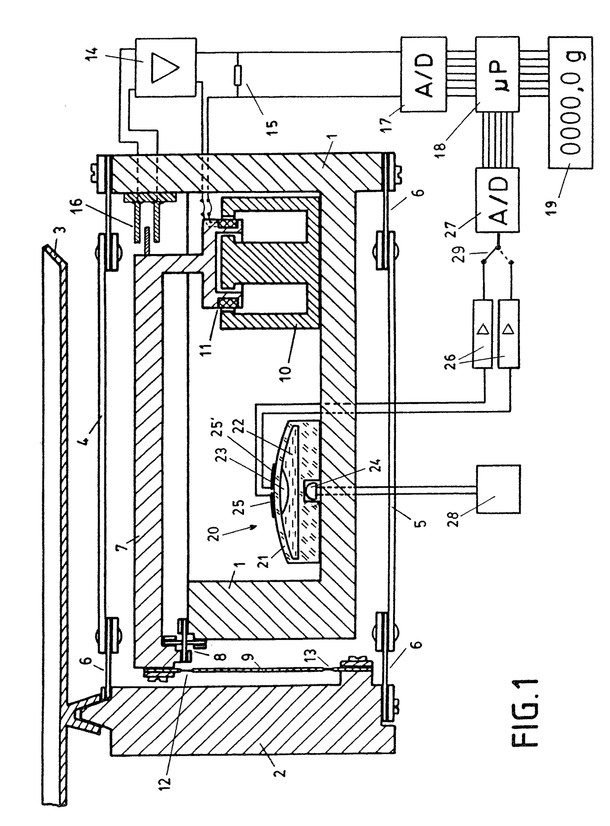
[0031]FIG. 7 shows the scale, in which the inclinometer 40 is embodied as an arrangement with two accelerometers 41 and 42, which are built into the scale inclined at 45° to the horizontal. The accelerometers are shown only schematically in FIG. 7. These may be fashioned as micromechanically manufactured components, such as those known from automobile construction, as accelerometers / crash sensors. The voltage supply to the accelerometers 41 and 42 is not shown in FIG. 7, for reasons of clarity. The output signals from the accelerometers 41 and 42 are conducted via the signal lines 43 and 44 to amplifiers 26 and then digitized by the analog / digital converter 27. From the difference between the two signals, the tilt of the scale can be determined in a known manner and, from the sum of the two signals, the size of the gravitational acceleration / vibrations can be derived, as described above. The parts of the scale that have not been described are identical or analogous and are identifie...

third embodiment

[0032]FIG. 8 shows the scale. In this embodiment, a pendulum 51 is built into the scale as the inclinometer 50, wherein the pendulum 51 is suspended via a flexible element 52 from the system support 1 of the scale. Two strain gauges 53 and 54 are applied to the flexible element 52, the signal from the strain gauges being fed via the (only schematically indicated) lines 55 and 56 to the amplifiers 26 and the analog / digital converter 27. If the scale is tilted, the two strain gauges 53 and 54 are differently stretched or compressed, so that a difference signal is produced. The two strain gauges 53 and 54 are stretched in the same direction due to the weight of the pendulum 51, wherein the amount of stretching is proportional to the gravitational acceleration. The cumulative signal from the two strain gauges is therefore proportional to the prevailing gravitational acceleration. The remaining parts of the scale of FIG. 8 are identical or analogous to the similarly identified parts of t...


PUM


Abstract

An electronic scale having a measuring sensor (1 . . . 16), a digital signal processing unit (18), a digital display (19) and an inclinometer (40). The inclinometer derives a signal for the tilt of the scale from the difference of at least two signals. The digital signal processing unit (18) is provided with an additional circuit component or program routine that adds the two signals and, by way of this cumulative signal, corrects the vibration-distorted signal of the measuring sensor (1 . . . 16). A plurality of inclinometers enables the simultaneous detection of momentary gravitational acceleration. For example, in an electric bubble level, the gas bubble moves out of place when tilted and the diameter of the gas bubble changes when the gravitational acceleration changes. The scale thus provides an additional signal for correcting the influence of disturbances with minimum complexity.

Description

[0001]This is a Continuation of International Application PCT / EP2007 / 009619, with an international filing date of Nov. 7, 2007, which was published under PCT Article 21(2) in German, and the complete disclosure of which, including amendments, is incorporated into this application by reference.FIELD AND BACKGROUND OF THE INVENTION[0002]The invention relates to an electronic scale comprising a measuring sensor, a digital signal processing unit, a digital display and an inclinometer, said inclinometer deriving a signal for the tilt of the scale from the difference of at least two signals.[0003]Scales of this type are generally known and are described, for example, in DE 32 34 372C2 (which corresponds to U.S. Pat. No. 4,494,620). The electrical signal from the inclinometer is used, employing digital means, to correct the error in the scale caused by the cosine effect when it is tilted. This means that the scale no longer has to be placed in an exactly horizontal orientation through the ...

Claims


Application Information

Patent Timeline
Patent Type & Authority Patents(United States)
IPC IPC(8): G01G23/01G01G7/00
CPCG01G23/002G01G23/10
Inventor FREYDANK, GERDGRAF, WINFRIEDOLDENDORF, CHRISTIAN
Owner SARTORIUS LAB INSTR GMBH & CO KG
Why Eureka
Try Eureka