Two-step VCO calibration method

a two-step, vco technology, applied in the direction of pulse automatic control, instrumentation, electrial characteristics varying frequency control, etc., can solve the problems of large requirement of charge-pump dynamic range, increase of power consumption, critical layout size, etc., to achieve small gain of vco, short calibration time, and small size of passive loop filter

Active Publication Date: 2011-03-15
MICROCHIP TECH INC
View PDF7 Cites 7 Cited by
  • Summary
  • Abstract
  • Description
  • Claims
  • Application Information

AI Technical Summary

Benefits of technology

[0009]It is an object of the present invention to provide a two-step VCO calibration method. Comparing to the prior arts, the two-step method has the advantages of covering all the variation of process and temperature, shorter calibration time, smaller gain of VCO, pretty smaller size of passive loop filter, less operating power consumption.

Problems solved by technology

Therefore the layout size becomes a critical issue in circuit design.
This will lead a large requirement of charge-pump dynamic range.
Nevertheless, due to the calibration must be done before packet start, an extra and long calibration time should be needed at each packet resulting in the increase of power consumption.

Method used


Image

  • Two-step VCO calibration method
  • Two-step VCO calibration method
  • Two-step VCO calibration method

Examples


Embodiment Construction

[0025]Although the invention has been explained in relation to several preferred embodiments, the accompanying drawings and the following detailed description are the preferred embodiment of the present invention. It is to be understood that the following disclosed descriptions will be examples of present invention, and will not limit the present invention into the drawings and the special embodiment.

[0026]Hereinafter, a special method embodiment is detailed.

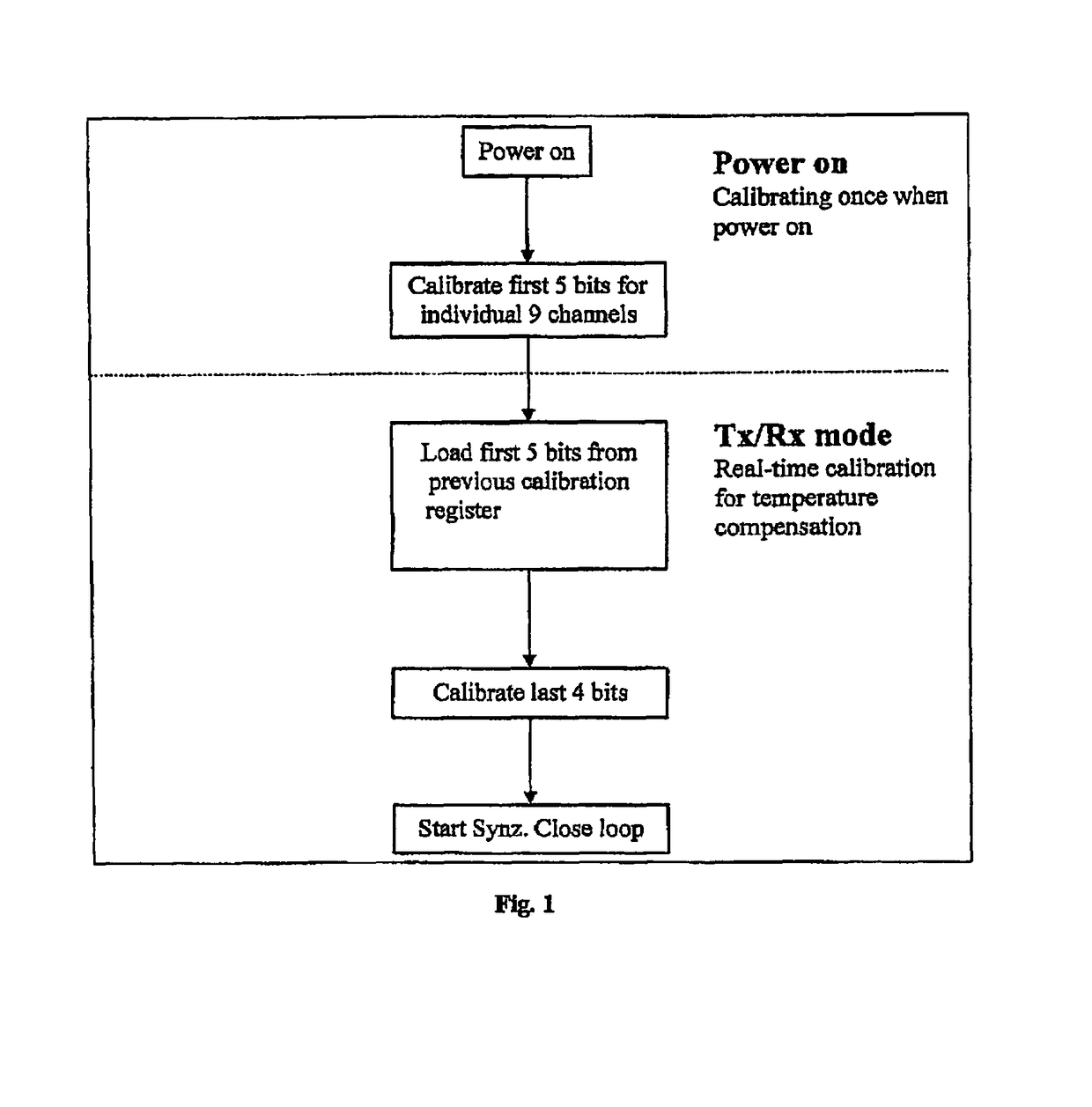
[0027]FIG. 1 is a flow-diagram of the two-step VCO calibration method according to the present invention. The two-step VCO calibration method comprises power-on calibration, used to calibrate first 5 bits for individual 9 channels and provide a coarse step of VCO tuning; real-time calibration, used to calibrate last 4 bits and provide a real-time calibration with fine VCO tuning. After the real-time calibration, analog phase lock loop starts to lock to wanted frequency.

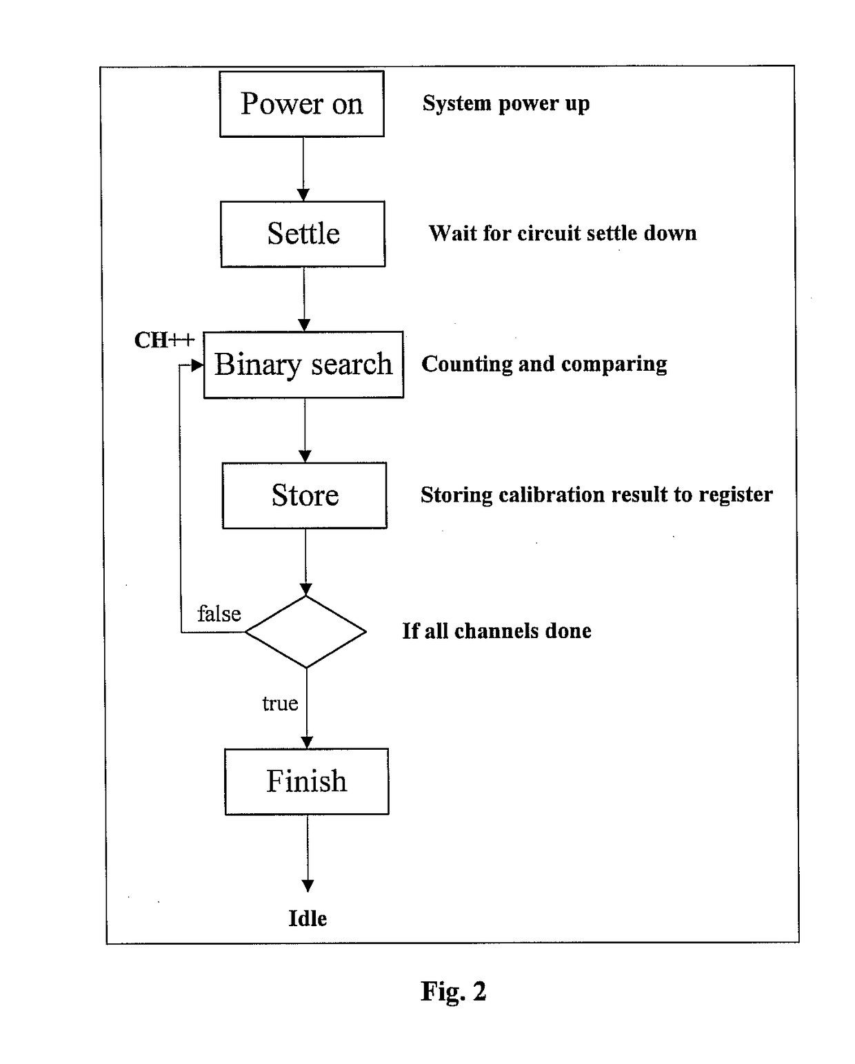
[0028]FIG. 2 is a flow-diagram of power-on calibration accor...


PUM


Abstract

The present invention discloses a two-step VCO calibration method. The two-step VCO calibration method, comprising power-on calibration, used to provide a coarse VCO tuning; real-time calibration, used to provide a fine VCO tuning according to the loaded result of said power-on calibration. The two-step VCO calibration method according to the present invention can cover all the variation of process and temperature and gain the advantages of shorter calibration time, smaller gain of VCO, pretty smaller size of passive loop filter and less operating power consumption.

Description

BACKGROUND OF THE INVENTION[0001]1. Field of the Invention[0002]The present invention relates to a method to coarse-tune the center frequency of integrated VCO(Voltage Control Oscillator), and more particularly, to a two-step VCO calibration method.[0003]2. Description of the Related Art[0004]In SOC (system on chip) field, all the functional blocks should be integrated to a single chip. Therefore the layout size becomes a critical issue in circuit design. Generally phase lock loop (PLL) block design contains VCO, divider, phase / frequency detector, charge-pump and passive loop filter, and among this block, passive loop filter will occupy the largest area if a medium loop band-width is selected. In order to reduce the die area due to this large capacitor for providing lower frequency pole, the gain of VCO must be lower to afford less use of passive capacitor. On the other hand once the gain of VCO lower, there is no margin for temperature variation of integrated VCO. So, there is the ...

Claims


Application Information

Patent Timeline
Patent Type & Authority Patents(United States)
IPC IPC(8): G01R23/00
CPCH03L7/099
Inventor CHEN, YI-LUNG
Owner MICROCHIP TECH INC
Why Eureka
Try Eureka