Positioning apparatus, exposure apparatus and device manufacturing method in which a correction unit corrects a value measured by a selected measuring device

a technology of exposure apparatus and correction unit, which is applied in the direction of process and machine control, program control, instruments, etc., can solve the problems of geometrically difficult to lay out the light beam axis, the problem of switching error of several nm, and the decrease of the dynamic characteristic of the control system of the stage. , to achieve the effect of suppressing measurement errors

Active Publication Date: 2011-03-15
CANON KK
View PDF11 Cites 9 Cited by
  • Summary
  • Abstract
  • Description
  • Claims
  • Application Information

AI Technical Summary

Benefits of technology

[0011]The present invention has been made in consideration of the above problems, and has as its object to suppress measurement errors due to the acceleration / deceleration of a stage in a positioning apparatus.
[0013]According to the present invention, it is possible to suppress measurement errors due to the acceleration / deceleration of a stage in a positioning apparatus.

Problems solved by technology

However, to move the stage with a long stroke in this system, it is necessary to attach an interferometer with a large mirror to the stage.
This results in a decrease in the dynamic characteristic of a control system of the stage.
From the viewpoint of the arrangement relationship with a projection lens, it is geometrically difficult to lay out the light beam axis of one interferometer, such that it allows measurement in the whole movable region of the stage.
Unfortunately, the prior art causes errors due to the switching between, for example, measuring devices, such as interferometers, during stage acceleration / deceleration, because the stage deforms.
In a stage of, for example, a semiconductor exposure apparatus, even a switching error of several nm often becomes problematic.
However, it is unavoidable that a stage top plate and a measurement reference mirror, arranged on it, deform during stage acceleration / deceleration.
When laser interferometers are switched while the mirror has deformed, the shape of the mirror irradiated with a laser beam changes between the acceleration time, the constant velocity time, and the stop time, resulting in switching errors.
Repeating switching during acceleration / deceleration accumulates switching errors.

Method used


Image

  • Positioning apparatus, exposure apparatus and device manufacturing method in which a correction unit corrects a value measured by a selected measuring device
  • Positioning apparatus, exposure apparatus and device manufacturing method in which a correction unit corrects a value measured by a selected measuring device
  • Positioning apparatus, exposure apparatus and device manufacturing method in which a correction unit corrects a value measured by a selected measuring device

Examples


first embodiment

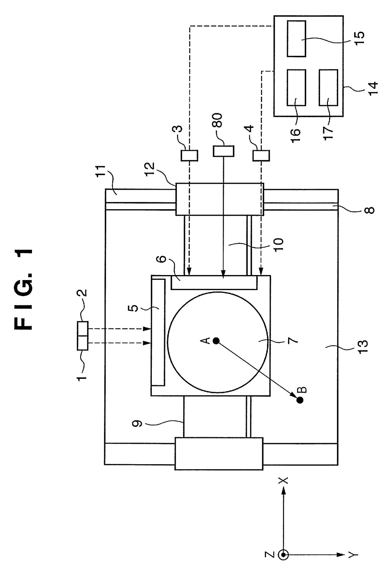
[0034]FIG. 1 is a view showing a positioning apparatus according to the first preferred embodiment, and, particularly, exemplifies a case wherein this apparatus is applied to a wafer stage 7 of a semiconductor exposure apparatus. The wafer stage 7 can move in the X and Y directions orthogonal to each other on its surface, and in the Z direction perpendicular to both the X and Y directions. The wafer stage 7 supports a Y mirror 5, an X mirror 6, and a wafer chuck (not shown). Although FIG. 1 shows a wafer stage 7 which can be driven in the X-, Y-, and Z-axis directions for descriptive convenience, it may be driven in six-axis directions. The mirror 6 is used to measure the coordinate position of the wafer stage 7 in the X-axis direction by reflecting a measurement light beam from an X-axis interferometer 3 or 4. The X-axis interferometers 3 and 4 are measuring devices, which are spaced apart from each other along the Y direction and measure the position of the wafer stage 7 in the X ...

second embodiment

[0051]FIG. 10 is a view showing another positioning apparatus according to a preferred embodiment of the present invention, and, especially, exemplifies a case wherein this apparatus is applied to a wafer stage 7 of a semiconductor exposure apparatus. The same reference numerals as those in the first embodiment denote parts having the same functions in the second embodiment. The positioning apparatus shown in FIG. 10 is different from that shown in FIG. 1 in that a plurality of interferometer axes lie in the X-axis direction in FIG. 1, but they lie in the Z-axis direction in FIG. 10. The Y mirror 5, shown in FIG. 1, corresponds to a YZ1 mirror 901 in FIG. 10. The YZ1 mirror 901 also serves as a bar mirror for reflecting a measurement light beam from the first Z-axis laser interferometer in the Z-axis direction in FIG. 10. Furthermore, a Z2 mirror 902 is arranged on the opposite side of the YZ1 mirror 901 and reflects a measurement light beam from the second Z-axis laser interferomet...


PUM


Abstract

A positioning apparatus, which positions a stage, includes a measurement system that measures a position of the stage. The measurement system includes a plurality of measuring devices that are spaced apart from each other along a first direction and measure a position of the stage in a second direction. A switching unit switches between the measuring devices to measure the position of the stage when the stage moves in at least the first direction. A correction unit corrects, based on an acceleration of the stage, the value measured by the measurement system. When the switching unit switches between the plurality of measuring devices, the correction unit corrects, based on a value obtained by the correction, a value measured by a measuring device after the switching.

Description

[0001]This application claims the benefit of Japanese Application No. 2006-290262, filed Oct. 25, 2006, which is hereby incorporated by reference herein in its entirety.BACKGROUND OF THE INVENTION[0002]1. Field of the Invention[0003]The present invention relates to a positioning apparatus.[0004]2. Description of the Related Art[0005]Along with the recent advance of the information-oriented society, the degrees of integration of, for example, devices and circuits are rapidly increasing. The development of micropatterning technologies has attained such an increase in the degrees of integration. For example, Japanese Patent Laid-Open No. 10-289943 discloses a system which controls a stage using a laser interferometer. This system incorporates an interferometer for measuring the position of the stage, so that one driving axis of the stage corresponds to one measurement light beam axis.[0006]However, to move the stage with a long stroke in this system, it is necessary to attach an interf...

Claims


Application Information

Patent Timeline
Patent Type & Authority Patents(United States)
IPC IPC(8): G01B9/02
CPCG05B19/404G05B2219/37287G05B2219/45031B23Q1/26G05B19/402G05B2219/37608H01L21/682
Inventor SEKIGUCHI, HIROYUKI
Owner CANON KK
Why Eureka
Try Eureka