Access control system with symbol recognition

a symbol recognition and access control technology, applied in the field of access control, can solve the problems of difficult to use lost or stolen the simplest security element is typically the hardest to automate reliably, and the difficulty of losing or stealing cards to access the system

Inactive Publication Date: 2011-03-15
HONEYWELL SILENT WITNESS
View PDF20 Cites 34 Cited by
  • Summary
  • Abstract
  • Description
  • Claims
  • Application Information

AI Technical Summary

Benefits of technology

[0017]The system may also be automated using face and / or voice verification software to eliminate the need for a remote security guard at the access control computer.

Problems solved by technology

The “who you are” element of security is typically the hardest to automate reliably.
However “who you are” is not transferable to other individuals, in contrast to the other two elements of validating access which are easily transferred, and so more easily compromised.
Such systems make it very difficult for lost or stolen cards to be used to access the system.
A common problem with any automated access control system is known as ‘piggy backing’.
The alternative of having a security guard at each access point is costly and not a very good utilization of the security guard's time.
The two-camera design requires additional equipment expenses, as well as additional processing and bandwidth overhead.
Also, the Williams apparatus is directed to photographic identification badges, which are at a greater risk of forgery than bar codes or symbol badges that link to an information database.
Lastly, the Williams apparatus is designed to be controlled by an operator, and automating the apparatus would expose it to a security breach due to the forgery possibilities described above.
A further disadvantage of systems such as magnetic card readers and the Williams apparatus is that they require physical contact with the card and so require periodic maintenance to function reliably.
They are also subject to tampering and vandalism.
While this type of motion detection is commonly used, it is inefficient and unwieldy for security purposes in areas that require regular access from security-cleared personnel.

Method used


Image

  • Access control system with symbol recognition
  • Access control system with symbol recognition
  • Access control system with symbol recognition

Examples


Embodiment Construction

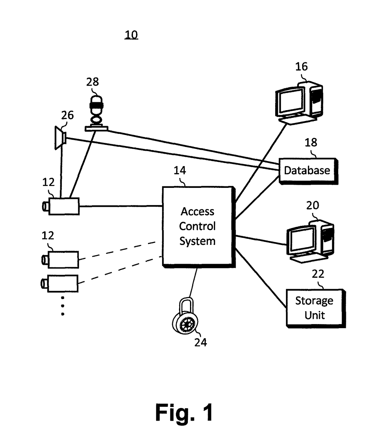
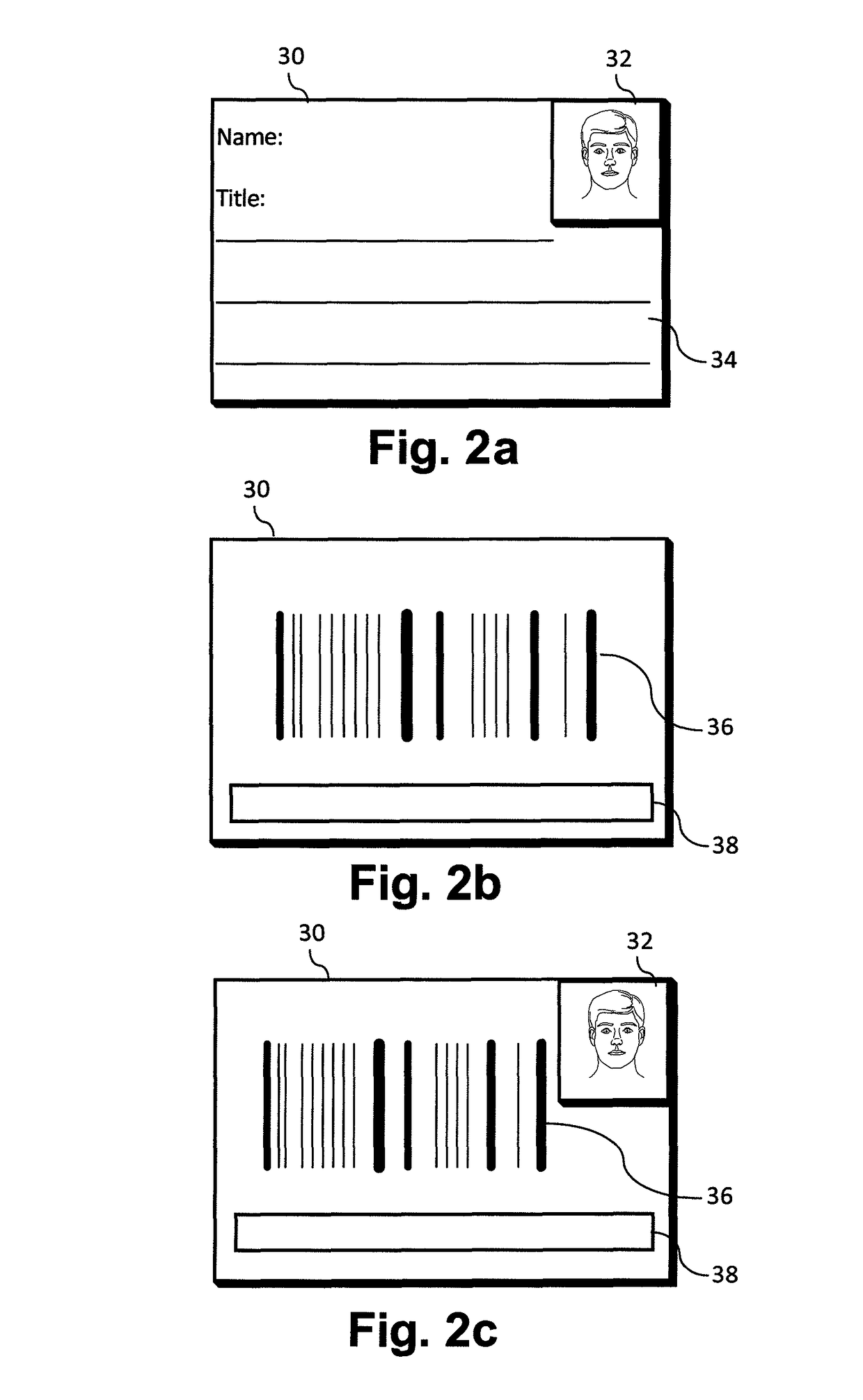
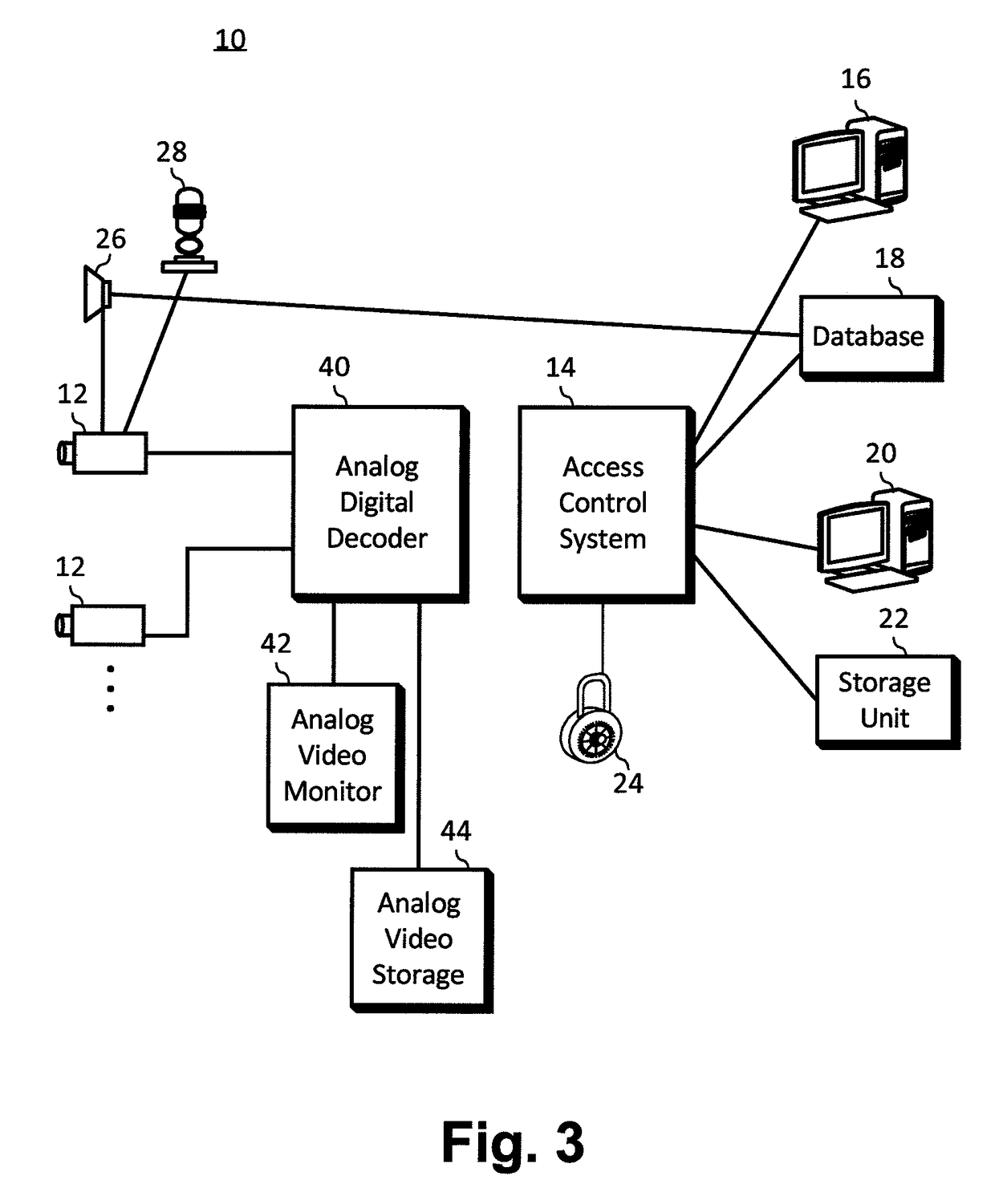
[0024]The access control system 10 diagrammed in FIG. 1 consists of a camera 12 connected to a computer network 14. The camera 12 is designed to take digital images of identity (ID) badges 30 (shown in FIGS. 2a, 2b, and 2c) and individuals with its field of view. Also connected to the computer network 14 are a badge reading computer 16, a database 18, and an access control computer 20.

[0025]In operation, the camera 12 scans an ID badge 30 (shown in FIG. 2a) and sends the resulting digital image into the computer network 14. The badge reading computer 16 interprets the bar code 36 on the ID badge 30 and retrieves information about the badge and badge holder from the database 18. The database information is passed to the access control computer 20 where an operator determines if access is to be allowed. Alternatively, the access control computer 20 can retrieve the information from the database 18 after receiving the bar code interpretation from the badge reading computer 16. The digi...


PUM


Abstract

A video camera is located at a secure access point and is connected to a computer network. The camera is used as a conventional security camera and also provides automated assistance with access control. When an identity badge is presented to the camera by a person requesting access to the facility, a computer that is monitoring the camera recognizes a bar code or other symbols on the badge and accesses a database to locate information associated with that identity badge. This information is then used to determine if the person should be granted access.

Description

FIELD[0001]The invention is in the field of access control, namely preventing unauthorized individuals from entering secured areas, or from accessing secured information, or from performing privileged transactions.BACKGROUND[0002]In the following discussion, the term ‘secured area’ is used generically to refer to any type of physical or virtual facility having privileged access, such as the rooms of a secure facility, or information on a computer, or functions of a computer, or the privilege to perform financial transactions. The term ‘user’ is used to refer to a person attempting to access a secured area.[0003]The purpose of an access control system is to determine if a person attempting to enter a secured area is authorized to do so. There are three basic elements to validating access privileges, which can be simply summarized as “who you are”, “what you know”, and “what you have”. Each of these elements has strengths and weaknesses. Therefore, a given access control system might ...

Claims


Application Information

Patent Timeline
Patent Type & Authority Patents(United States)
IPC IPC(8): G06K9/00H04N7/18H04N9/47G06K19/08G07C9/00
CPCG06K19/08G07C9/00079G07C9/00111H04N7/181G07C9/253G07C9/28
Inventor WILSON, JEREMY CRAIGBLACK, DAVID
Owner HONEYWELL SILENT WITNESS
Why Eureka
Try Eureka