Receiver without phase locked loop frequency synthesizer and receiving method using the same

a technology of phase lock loop frequency synthesizer and receiver, which is applied in the direction of selective content distribution, television systems, instruments, etc., can solve the problems of increasing current consumption, battery life decline, increasing cost, etc., and achieves the effect of simplifying the system, reducing the layout area of the chip, and reducing the current consumption

Inactive Publication Date: 2011-03-15
SAMSUNG ELECTRONICS CO LTD
View PDF19 Cites 6 Cited by
  • Summary
  • Abstract
  • Description
  • Claims
  • Application Information

AI Technical Summary

Benefits of technology

[0011]An aspect of the present invention is to provide a receiver that uses a digital channel filter instead of a PLL frequency synthesizer so as to reduce a layout area of a chip, simplify a system, and reduce the current consumption, and to a receiving method using the same.

Problems solved by technology

In the above-described receiver, the PLL frequency synthesizer used for such a receiver occupies a large proportion of the chip layout area, thereby increasing its cost.
Further, since the PLL frequency synthesizer needs many blocks, such as a VCO, a loop filter, and a frequency divider, the current consumption increases.
As a result, when the PLL frequency synthesizer is used in a portable device, its battery life decreases.
Also, the manufacturing process is more complicated.

Method used


Image

  • Receiver without phase locked loop frequency synthesizer and receiving method using the same
  • Receiver without phase locked loop frequency synthesizer and receiving method using the same
  • Receiver without phase locked loop frequency synthesizer and receiving method using the same

Examples


Embodiment Construction

[0025]Advantages and aspects of the present invention and methods of accomplishing the same may be understood more readily by reference to the following detailed description of exemplary embodiments and the accompanying drawings. The present inventive concept may, however, be embodied in many different forms and should not be construed as being limited to the exemplary embodiments set forth herein. Rather, these exemplary embodiments are provided so that this disclosure will be thorough and complete and will fully convey the concept of the invention to those skilled in the art, and the present invention will only be defined by the appended claims. Like reference numerals refer to like elements throughout the specification.

[0026]Exemplary embodiments of the present invention will now be described more fully with reference to the accompanying block diagrams and flows charts, in which exemplary embodiments of the invention are shown.

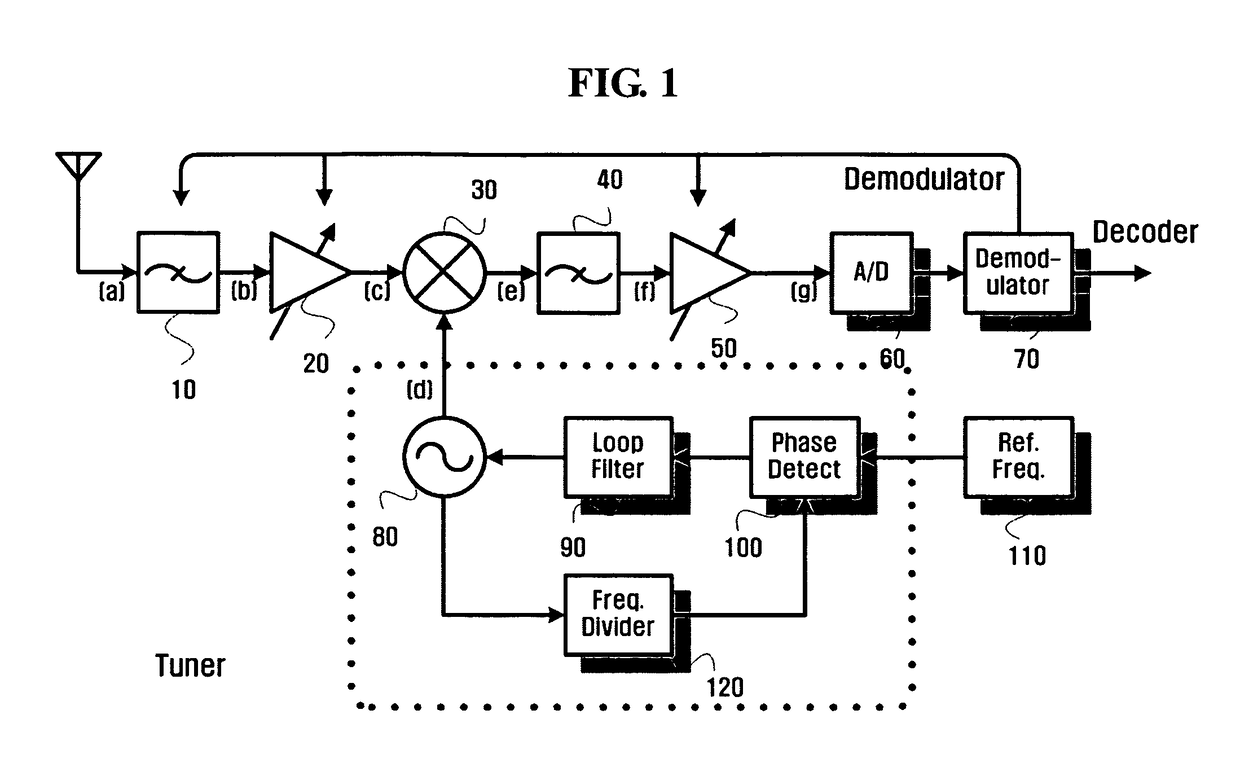
[0027]FIG. 3 is a view showing the configuration of a...


PUM


Abstract

A receiver implemented without using a phase locked loop frequency synthesizer and a receiving method of a receiver implemented without using a phase locked loop frequency synthesizer are provided. The receiver includes a radio frequency (RF) receiving unit; a band-selecting unit; an RF amplifier; a local oscillation (LO) signal generator; a mixer; an IF amplifier; an analog to digital (A / D) converter; and a channel-selecting unit. The method includes passing a frequency band of a radio frequency (RF) signal received by an RF receiving unit; amplifying the passed RF signal; generating a local oscillation (LO) signal having a fixed frequency; mixing the LO signal with the amplified RF signal to lower the frequency of the amplified RF signal; outputting an intermediate frequency (IF) signal; amplifying the IF signal; converting the amplified IF signal into a digital signal; and selectively passing frequencies of the digital signal corresponding to a specific channel.

Description

CROSS-REFERENCE TO RELATED APPLICATION[0001]This application claims priority from Korean Patent Application No. 10-2005-0099229 filed on Oct. 20, 2005 in the Korean Intellectual Property Office, the disclosure of which is incorporated herein by reference in its entirety.BACKGROUND OF THE INVENTION[0002]1. Field of the Invention[0003]Apparatuses and methods consistent with the present invention relate to a receiver and a receiving method, and, in particular, to a receiver that uses a digital channel filter capable of controlling a center frequency according to a selected channel, instead of a phase locked loop (PLL) frequency synthesizer having a complicated block configuration and thus a high current consumption, so as to improve the efficiency.[0004]2. Description of the Related Art[0005]Digital Multimedia Broadcasting (DMB) is a digital wireless communication service that provides multimedia content through a microwave band currently used for analog television (TV) broadcasts. In ...

Claims


Application Information

Patent Timeline
Patent Type & Authority Patents(United States)
IPC IPC(8): H04B7/08H04B1/18H04B1/26H04N5/44
CPCH04B1/001H04N5/4446H04N21/4383H04N5/50H04N5/455H04B1/16H04B1/40
Inventor LEE, JEONG-HOPARK, JOONG-SUK
Owner SAMSUNG ELECTRONICS CO LTD
Why Eureka
Try Eureka