Stacked capacitor memory

a capacitor memory and capacitor technology, applied in the direction of digital storage, diodes, instruments, etc., can solve the problems of reducing the chip area, reducing the efficiency of the diode, and reducing the cost of manufacturing

Inactive Publication Date: 2007-08-09
KIM JUHAN
View PDF0 Cites 36 Cited by
  • Summary
  • Abstract
  • Description
  • Claims
  • Application Information

AI Technical Summary

Benefits of technology

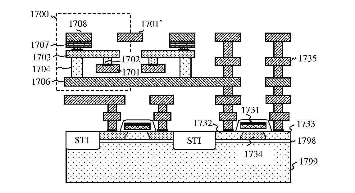
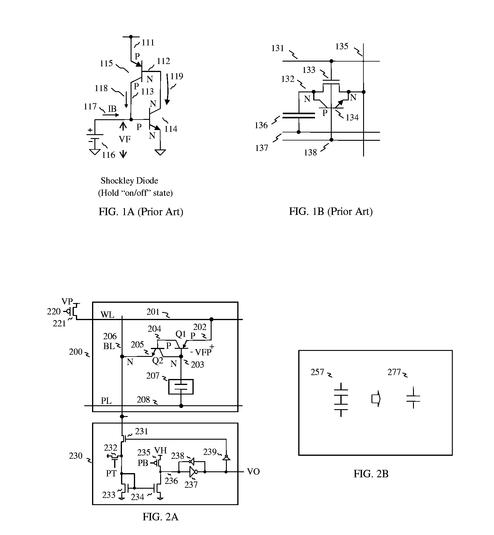
[0012]In the present invention, stacked capacitor memory is realized, wherein the memory cell is formed in between the routing layers on the wafer in order to reduce chip area. Also the memory cell can be formed on the MOS transistor because the memory cell includes a four-terminal diode access device and a storage capacitor, which combination is less complicated to fabricate with additional process steps in the current CMOS process environment, compared to fabricating the conventional memory including the MOS transistor as an access device.

Problems solved by technology

And high current flowing eventually raises operating temperature by “Joule heating”, which produces more junction leakage and gate leakage.
Consequently, the data stored in the diode can be lost quickly by those leakages.
However diode can not easily replace the MOS device as an access device because it has unidirectional current control characteristic and internal feedback loop.
Conversely, using diode as an access device gives the bit line loading to the word line through diode, which makes the word line loading very heavy, but it is controllable to design with strong driver or segmentation for the word line.
Memory read cycle was very slow because each read cycle requires additional restore procedure.
Those consume high switching current and pumping current.
And MOS access transistor has subthreshold leakage current which is tricky and hard to reduce.
And one more undesirable effect is the parasitic bipolar transistor in the bottom side of the MOS transistor which should be suppressed by applying the negative voltage to the body.
These are major disadvantages of DRAM operation.
Moreover read operation is destructive which requires the write-back operation.
In consequence, DRAM operation is very slow.

Method used


Image

  • Stacked capacitor memory
  • Stacked capacitor memory
  • Stacked capacitor memory

Examples


Embodiment Construction

)

[0039]Reference is made in detail to the preferred embodiments of the invention. While the invention is described in conjunction with the preferred embodiments, the invention is not intended to be limited by these preferred embodiments. On the contrary, the invention is intended to cover alternatives, modifications and equivalents, which may be included within the spirit and scope of the invention as defined by the appended claims. Furthermore, in the following detailed description of the invention, numerous specific details are set forth in order to provide a thorough understanding of the invention. However, as is obvious to one ordinarily skilled in the art, the invention may be practiced without these specific details. In other instances, well-known methods, procedures, components, and circuits have not been described in detail so that aspects of the invention will not be obscured.

[0040]Detailed descriptions for the present invention are described as follows, which include the s...


PUM


Abstract

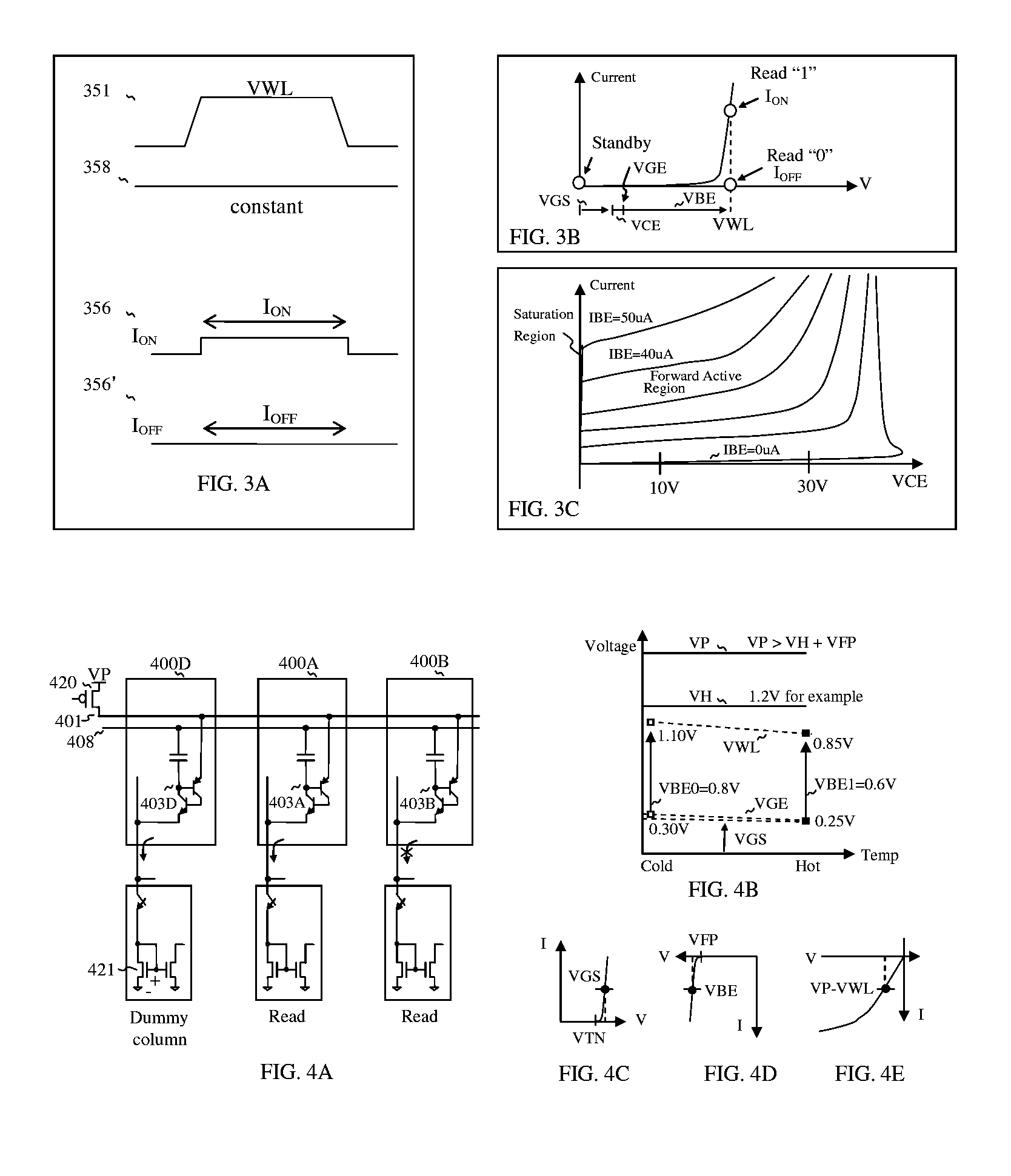
Stacked capacitor memory is realized, wherein a capacitor stores data and a diode serves as an access device instead of MOS transistor, the first terminal is connected to a word line, the second terminal is connected to the first electrode of the capacitor which serves as a storage node while the second electrode is connected to a plate line, the third terminal is floating, and the fourth terminal is connected to a bit line. When write, the storage node is charged or not, depending on the conducting state of the diode which is controlled by the bit line. When read, the diode also serves as a sense amplifier to detect whether the storage node is forward bias or not, and it sends binary data to a latch device wherein includes a current mirror and a feedback loop which cuts off the current path after latching, thus it reduces active current, minimizes data pattern sensitivity, and also rejects coupling noise. And dummy rows and columns generate replica delay signals which guarantee timing margin and reduce cycle time. And its applications are extended to single port, multi port and content addressable memory. In addition, the memory cells are formed in between the routing layers, which memory cells can be stacked over the transistor or another capacitor memory cell.

Description

FIELD OF THE INVENTION[0001]The present invention relates generally to integrated circuits, in particular to RAM (Random Access Memory) including capacitor storage element, and its applications, such as single port memory, multi port memory and CAM (content addressable memory).BACKGROUND OF THE INVENTION[0002]A p-n-p-n diode known as Shockley diode or thyristor, is a solid-state semiconductor device similar to two-terminal p-n diode, with an extra terminal which is used to turn it on. Once turned on, diode (p-n-p-n diode or n-p-n-p diode) will remain on conducting state as long as there is a significant current flowing through it. If the current falls to zero, the device switches off. Diode has four layers, with each layer consisting of an alternately p-type or n-type material, for example p-n-p-n and n-p-n-p. The main terminals, labeled anode and cathode, are across the full four layers, and the control terminal, called the gate, is attached to one of the middle layers. The operati...

Claims


Application Information

Patent Timeline
Patent Type & Authority Applications(United States)
IPC IPC(8): G11C15/00G11C11/36G11C11/24
CPCG11C7/02G11C7/14G11C11/22G11C11/405H01L27/1021G11C11/4099G11C15/043G11C2211/4016H01L27/0688G11C11/4074
Inventor KIM, JUHAN
Owner KIM JUHAN
Why Eureka
Try Eureka