Grain reaper

a technology for grains and threshers, applied in the direction of threshers, lighting and heating apparatus, drying solid materials, etc., can solve the problems of not configuring ideal equipment, high manufacturing cost, and limited machines

Active Publication Date: 2011-03-22
IND REUNIDAS COLOMBO LTD
View PDF31 Cites 9 Cited by
  • Summary
  • Abstract
  • Description
  • Claims
  • Application Information

AI Technical Summary

Benefits of technology

[0007]The first goal of the invention is the materialization of a double gathering roller, that is, two rollers that are axially aligned, a right one and a left one, both of which are appropriate to harvest aligned plants simultaneously, wherein each one is defined by a square tubular axis with cylindrical ends of axis for their bearing on the structure, the square axis of which having several discs that are distributed equidistantly, all of them provided with plates that are ordinarily triangular, radially placed, which configure gathering grips, each disc of which is preferentially provided with five plates or gathering grips, and, furthermore, the central portion of such disc is perforated by a star-like bore (toothed), so that the same may be placed in different angles regarding the four corners of said tube, consequently, the grips are also positioned in angles, in a different manner of each other, originating a substantially resistant set since the combination of various grips defines a vigorous gathering roller that is capable of resisting the aggressive work of harvesting the plants, even when the plants bring stones, land, thick branches and other matters. On the other hand, an even roller is also specially provided above the gathering roller to arrange and drive the plants to the concentrating set, which are two reverse threads designed to concentrate the gathered material and, at the same time, throw it into the subsequent set, which is the routing thread which, in turn, have the necessary means to drive and uniformly divide all the gathered material inside the two beating cylinders, placed longitudinally, assembled inside the respective thick screens (cylindrical sieve), where the bulkier unwanted material is retained, such as branches and leaves, peels and others, which step out directly from the mouths located at the end portion of the beating cylinders and driven to the sides of the machine, whereas the bean and other minor impurities drop by gravity on a vibrating sieve, wherein the grains are retained, whereas particles such as land, sand and the like passes through this sieve and drop by gravity on the ground, whereas the grains and small light particles are vibrated and shaken towards the posterior portion of the machine, wherein ventilators separate the light particles by means of suspension (suction), discarding them through other mouth that is turned to the back of the machine, while the entirely clean grains are driven to two posterior elevators, wherein they are driven until a grain bucket which, in turn, is assembled to laterally incline at the moment they are unloaded, the inclined motion of which is done hydraulically, the grain bucket of which furthermore is provided with openings so that the level of the grains may be seen and, in addition, is provided with a lateral inclined mouth to facilitate the unloading by free drop.
[0008]Therefore, it is noted that each set of said machine has had modifications so that, on the end, all of them have cooperated simultaneously to improve considerably the performance of the machine, featuring resources to further speed up the reaping process of various grain cultures, notably the bean and the peanut, further with additional technical and operational advantages, particularly regarding the operational simplicity, reduced maintenance and, consequently, it is obtained a considerable productivity increase.
[0010]The reaper of the present invention is classified as a trailered one and may be coupled with conventional tractors with power socket, hydraulic system and reduced gear. Either the coupling or the uncoupling is extremely easy and fast.

Problems solved by technology

However, some of these machines are limited and others have a really high manufacturing cost, not configuring an ideal equipment for medium and small producers.
On the other hand, the traditional machines have assembling details that wear out very easily, particularly regarding the gathering roller, which is responsible to rise and drive the aligned plants to the first branch concentrating set since, as it is known, one of the most demanded set of the machine is the gathering roller, wherein the grips must be carefully designed to be wear-resistant and chock-resistant in relation to the impact with other matters that are not plants.
Such a situation is not always easily dealt with by the conventional machines.
They consequently require frequently corrective and preventive maintenance, which rises considerably the final cost of the processed product.

Method used


Image

  • Grain reaper
  • Grain reaper
  • Grain reaper

Examples


Embodiment Construction

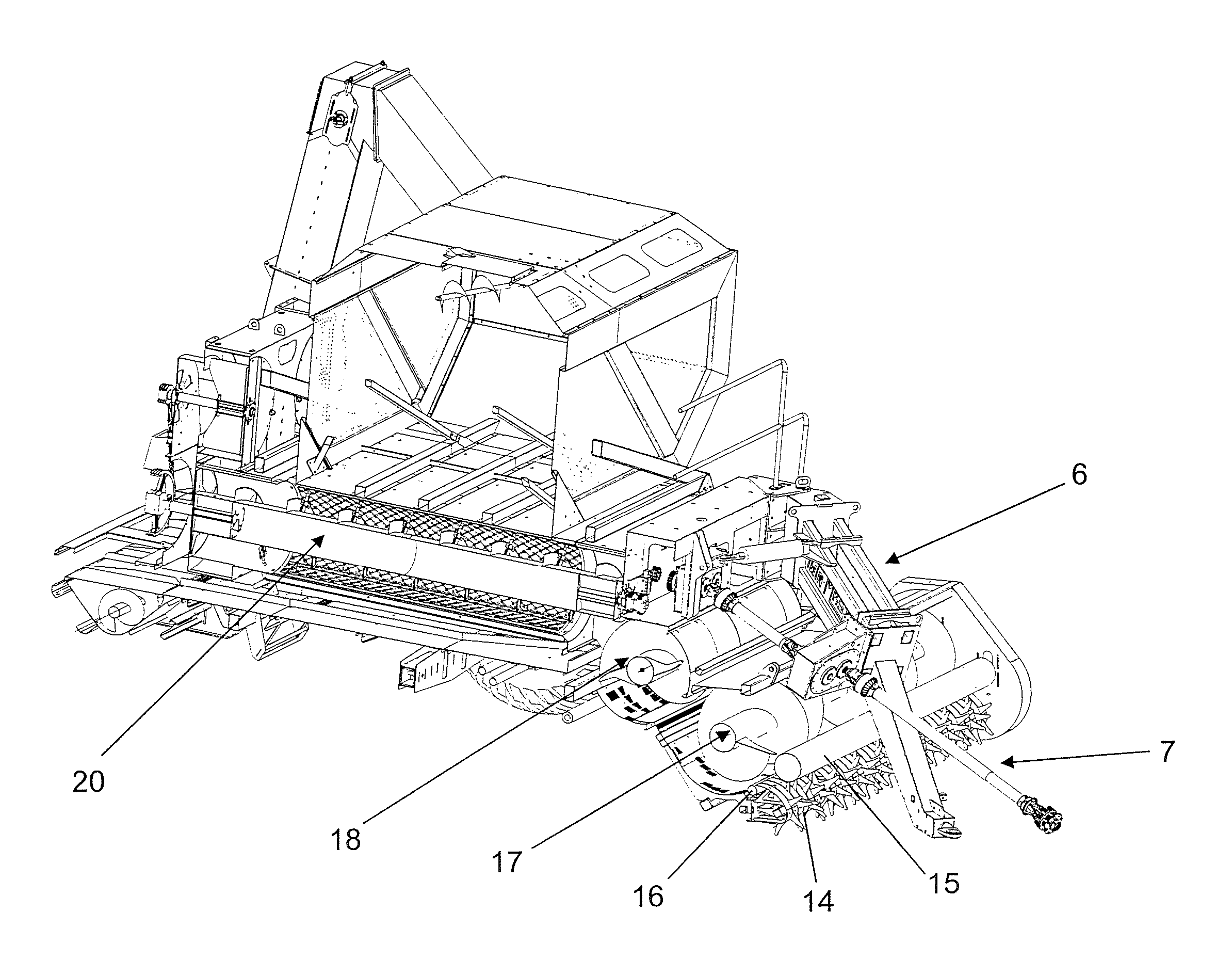
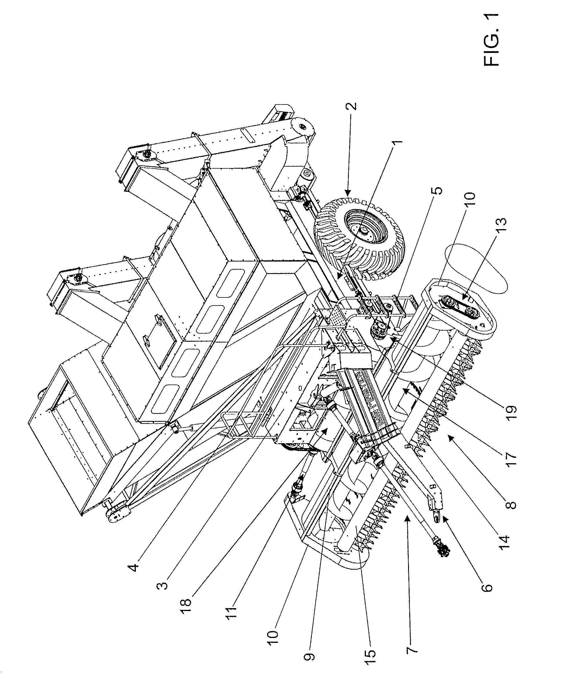
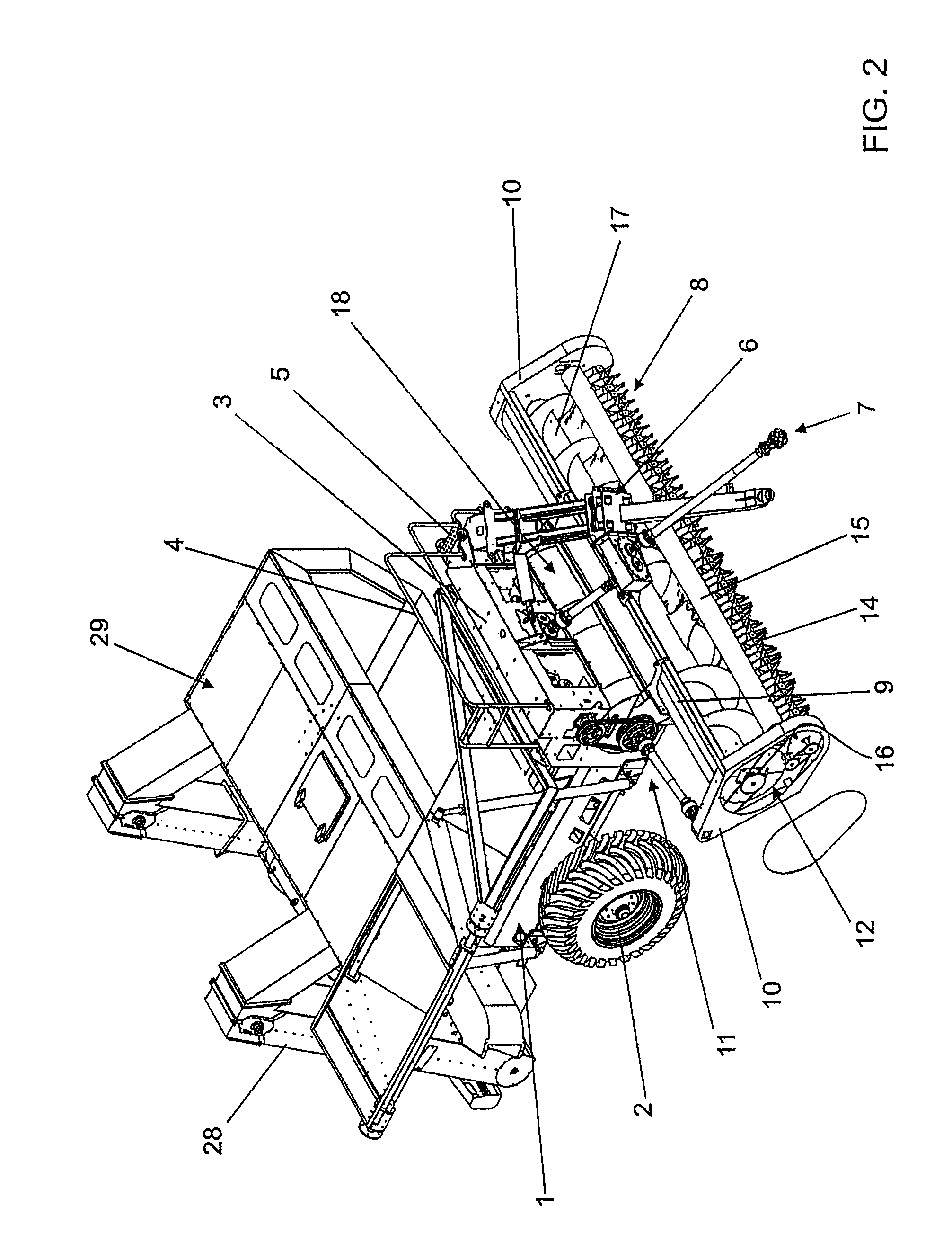
[0034]In FIGS. 1-3, the present invention is featured by initially comprising a box-shaped structural part (1) which is ordinarily with a parallelepiped form, in which all sets are aggregated, starting from its lower part, wherein the wheeling set (2) is mounted and, in the anterior part, a top passageway (3) is provided with a handrail (4) and side stair (5), as well as the set of the coupling shaft (6) with the tractor (not depicted) is mounted on the anterior part of said structure (1) and the first set of cardan takeoff (7) is aggregated inside of it, which stands under said sets and is mounted in the transversal direction regarding the structure (1), the double gathering set (8), which, in turn, has a supplementary structure (9) with box-shaped side portions (10), wherein other takeoff sets (11-12-13) are mounted in synchronization with the first takeoff (7) and, furthermore, the edges of three internal rotating sets are born among said boxes (10), one of which is lower positio...


PUM


Abstract

A reaper of grains is for reaping bean grains that is classified as a trailer. More specifically, a bean reaper for carrying out two different operations, the first one of which is gathering various plants, such as bean plants, peanuts and other grains, which have been previously plucked and aligned, whereas the second function of which is to perform a whole cleaning process by separating the grains (seeds) from the remaining unwanted parts.

Description

RELATED APPLICATION[0001]The present application claims priority to Brazilian Application No. PI0702108-9 filed May 28, 2007, which is incorporated herein in its entirety by reference.FIELD OF THE INVENTION[0002]The present invention relates to a reaper for grains, specially for the bean grains. More specifically, the present invention refers to technical and functional improvements specially developed and introduced in the subparts which configure a bean reaper that is classified as a trailer to carry out two different operations, the first one of which is gathering various plants, such as bean plants, peanuts and other grains, plants which are previously plucked and aligned, whereas the second function of which is to perform a whole cleaning process by separating the grains (seeds) from the remaining unwanted parts.BACKGROUND OF THE INVENTION[0003]There are currently several machines made for the above purposes, some of which are designed to harvest and clean the grains and others...

Claims


Application Information

Patent Timeline
Patent Type & Authority Patents(United States)
IPC IPC(8): A01D41/00A01F12/00
CPCA01D29/00A01D41/00A01D45/22
Inventor BERTINO, LUIZ HENRIQUE
Owner IND REUNIDAS COLOMBO LTD
Why Eureka
Try Eureka