Turbine engine with integrated generator having shared lubrication system

a turbine engine and lubrication system technology, applied in the direction of machines/engines, indirect heat exchangers, lighting and heating apparatus, etc., can solve the problems of pressure loss, interfering more, and causing the overheating of lubrican

Active Publication Date: 2011-03-22
RTX CORP
View PDF13 Cites 33 Cited by
  • Summary
  • Abstract
  • Description
  • Claims
  • Application Information

AI Technical Summary

Problems solved by technology

During such lubrications, heating of the lubricant is caused to occur due to mechanical energy losses in the lubricated apparatus.
Such a larger sized exchanger correspondingly requires larger fairings about that exchanger leading to a) possible detachment of the fan streams therefrom and the resulting vortex losses absent further preventive measures, b) a larger inlet to the duct possibly resulting in the “spilling” out of incoming air and the accompanying eddy and mixing losses, and to c) a larger range of required motion for the required larger size duct outlet flaps possibly leading to this flap interfering more with the fan airstream passing the outside of the flap when in the range of being nearly fully open to being fully closed.
These three consequences, even in an optimally configured arrangement, will result in pressure losses.
Thus, such an air and lubricating oil heat exchanger duct based system continually leads to thrust losses in the turbofan engine despite being unnecessary for cooling the lubricating oil in many flight situations.
Nevertheless, space for a further heat exchanger must be found to accommodate such an oil and oil heat exchanger.

Method used


Image

  • Turbine engine with integrated generator having shared lubrication system
  • Turbine engine with integrated generator having shared lubrication system
  • Turbine engine with integrated generator having shared lubrication system

Examples


Embodiment Construction

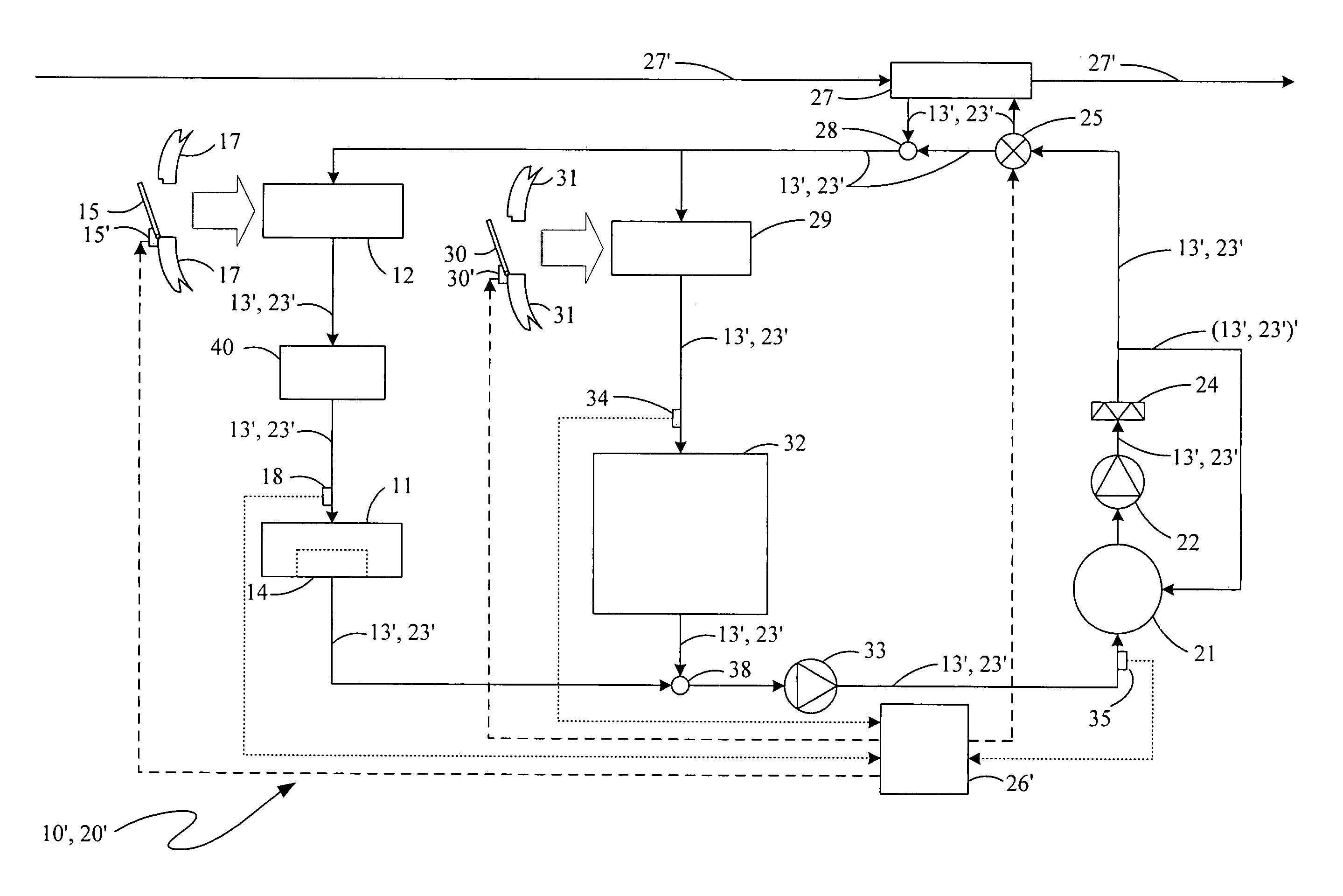
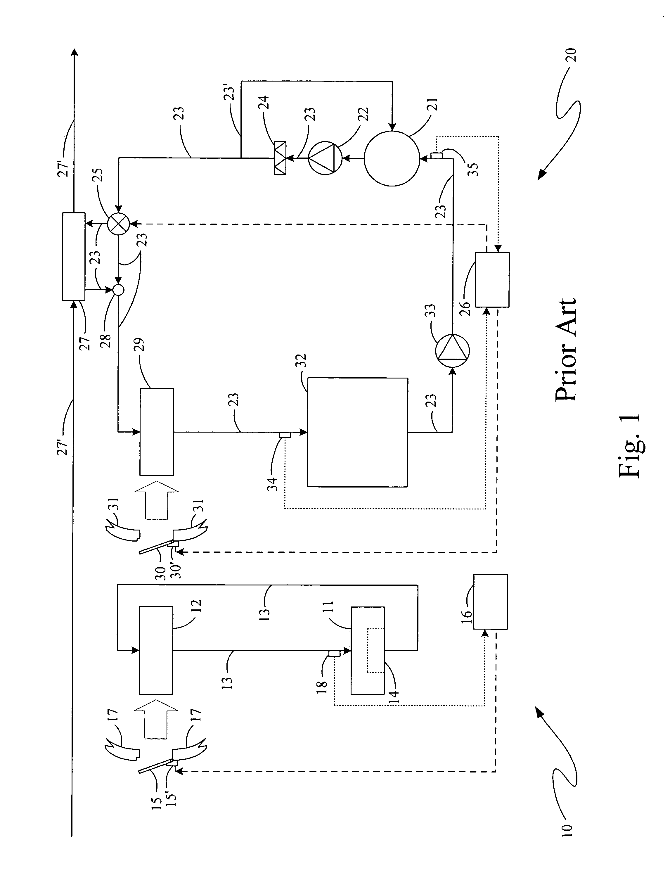
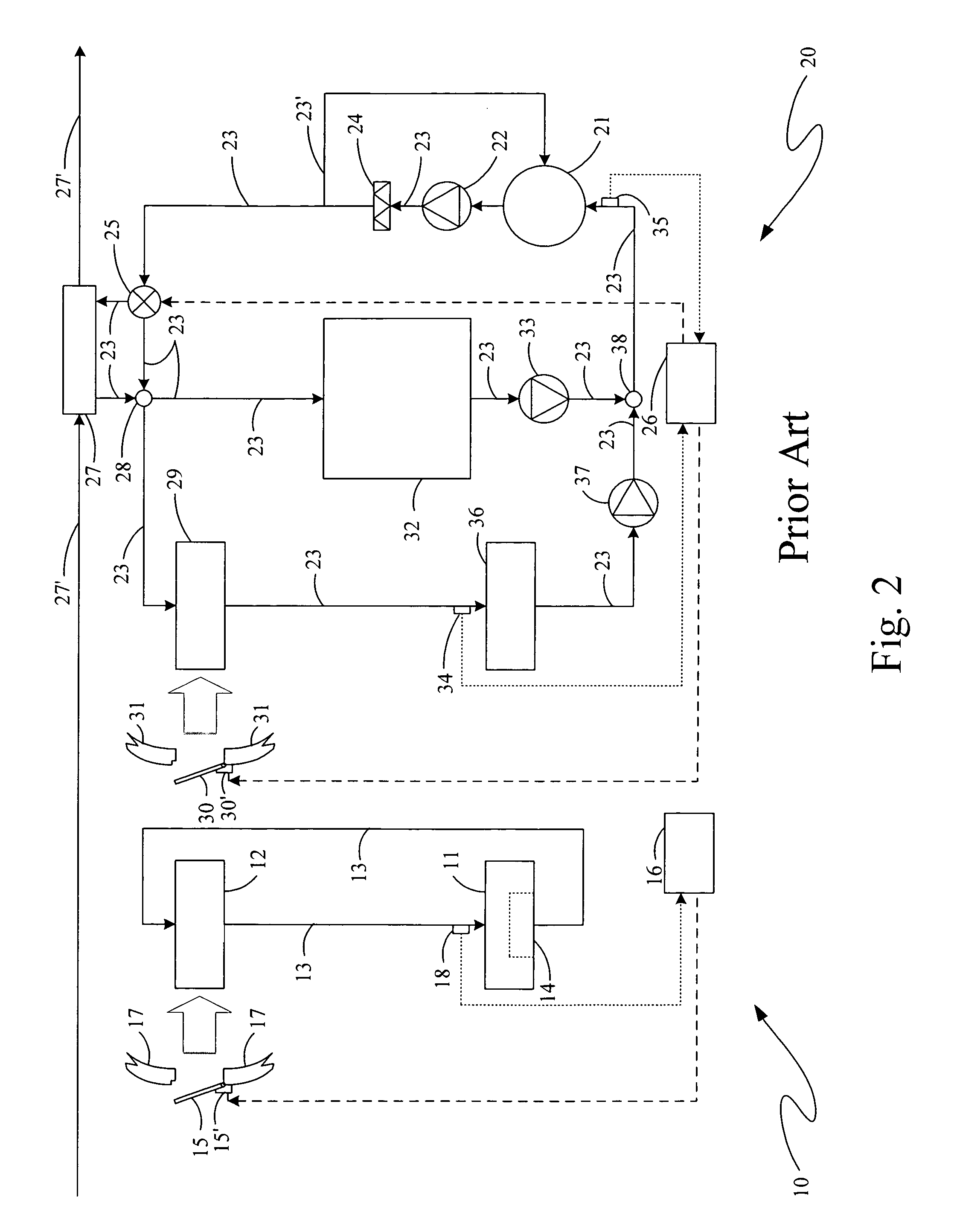
[0016]Lubrication systems typically in use currently with turbofan engines and associated integrated drive generator systems are represented in the schematic diagram shown in FIG. 1 where there is a lubrication system for the turbofan engine that is shown entirely separate from the lubrication system for the generator. Thus, on the left is shown a lubrication system, 10, for an integrated drive generator system having therein an electrical generator, 11, with a rotor that is forcibly rotated by the associated turbofan engine, and an air and oil heat exchanger, 12, interconnected to generator 11 with oil conduits, 13, allowing therethrough the circulation of the system lubricant, or the oil, through the moving parts of the generator such as bearings and through the plurality of oil carrying passageways of the exchanger about and between which secondary airstreams from the engine fan can flow, the oil being selectively forced to so circulate by a pump, 14, internal to generator 11.

[00...


PUM


Abstract

A heat exchange system for use in operating equipment having a plurality of subsystems in each of which a common working fluid is utilized to provide selected operations in that subsystem with a reservoir containing at least some of the common working fluid and has both a supply system and a return system connected between the reservoir and each of the plurality of subsystems through which any common working fluid in the reservoir can be conveyed. An airstream heat exchanger is provided connected in one of the supply and return systems so as to have the common working fluid conveyed therethrough cooled at selectively variable rates in the airstreams passing thereby during at least some such uses of the operating equipment.

Description

BACKGROUND OF THE INVENTION[0001]The present invention relates to lubrication systems for turbine engines and for associated integrated drive electrical power generator systems and, more particularly, to various outside fluid and lubricant heat exchangers for use in maintaining desired temperatures of the lubricants in such engines and systems.[0002]Lubrication systems for turbine engines and associated equipment, such as a turbofan engine and an associated integrated drive electrical power generator, provide pressurized lubricant, an oil, to lubricate, cool and clean the engine main bearings, gearbox gears, and the like. Similarly, pressurized oil is used for the lubrication of bearings and other parts in an associated integrated drive generator system. During such lubrications, heating of the lubricant is caused to occur due to mechanical energy losses in the lubricated apparatus. Thermal management of such lubricants is very important for continued successful operation of such lu...

Claims


Application Information

Patent Timeline
Patent Type & Authority Patents(United States)
IPC IPC(8): F02C7/06
CPCF01D15/10F01D25/12F01D25/125F01D25/18F02C7/06F05D2220/76F05D2260/234Y02T50/671Y02T50/675Y02T50/60
Inventor SCHWARZ, FREDERICK M.GLAHN, JORN A.
Owner RTX CORP
Why Eureka
Try Eureka